Chapter
13
Design Example
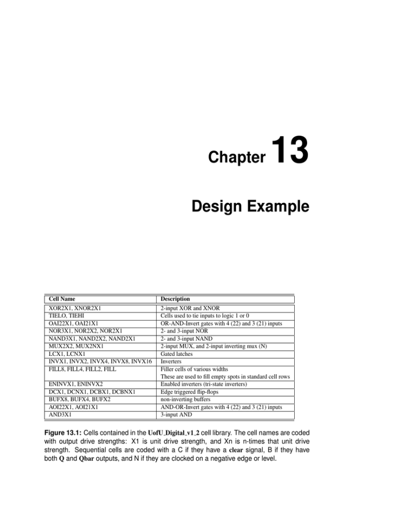
Cell Name
XOR2X1, XNOR2X1
TIELO, TIEHI
OAI22X1, OAI21X1
NOR3X1, NOR2X2, NOR2X1
NAND3X1, NAND2X2, NAND2X1
MUX2X2, MUX2NX1
LCX1, LCNX1
INVX1, INVX2, INVX4, INVX8, INVX16
FILL8, FILL4, FILL2, FILL
ENINVX1, ENINVX2
DCX1, DCNX1, DCBX1, DCBNX1
BUFX8, BUFX4, BUFX2
AOI22X1, AOI21X1
AND3X1
Description
2-input XOR and XNOR
Cells used to tie inputs to logic 1 or 0
OR-AND-Invert gates with 4 (22) and 3 (21) inputs
2- and 3-input NOR
2- and 3-input NAND
2-input MUX, and 2-input inverting mux (N)
Gated latches
Inverters
Filler cells of various widths
These are used to fill empty spots in standard cell rows
Enabled inverters (tri-state inverters)
Edge triggered flip-flops
non-inverting buffers
AND-OR-Invert gates with 4 (22) and 3 (21) inputs
3-input AND
Figure 13.1: Cells contained in the UofU Digital v1 2 cell library. The cell names are coded
with output drive strengths: X1 is unit drive strength, and Xn is n-times that unit drive
strength. Sequential cells are coded with a C if they have a clear signal, B if they have
both Q and Qbar outputs, and N if they are clocked on a negative edge or level.
260
CHAPTER 13: Design Example
#/* -*- c -*- */
#/**********************************************************************/
#/* Defaults can be found in $SYNOPSYS/admin/setup/.synopsys_dc.setup */
#/**********************************************************************/
set company {University of Utah}
set designer {Erik Brunvand}
#/**********************************************************************/
set plot_command {lpr -Pcsps}
set text_print_command {lpr -Pcsps}
set text_editor_command {emacs %s &}
set command_log_file "./synopsys-dc_shell.log"
set view_command_log_file "./synopsys-dc_shell-view.log"
set find_converts_name_lists "false"
#/**********************************************************************/
set SynopsysInstall [getenv "SYNOPSYS"]
# You can add to this search path if you have your libraries
# stored somewhere else...
set search_path [list . \
[format "%s%s" $SynopsysInstall /libraries/syn] \
[format "%s%s" $SynopsysInstall /dw/sim_ver] ]
#/* =================================================
#/* Define a work library in the current project dir
#/* to hold temporary files and keep the project area
#/* uncluttered. Note: You must create a subdirectory
#/* in your project directory called WORK.
#/* =================================================
define_design_lib WORK -path ./WORK
*/
*/
*/
*/
*/
*/
#/* ================================================= */
#/* General configuration settings.
*/
#/* ================================================= */
set hdlin_check_no_latch true
set compile_fix_multiple_port_nets true
set hdlin_translate_off_skip_text true
set verilogout_write_components true
set verilogout_architecture_name "structural"
set verilogout_no_tri true
set hdlin_translate_off_skip_text true
set bus_naming_style {%s[%d]}
set
set
set
set
target_library [list UofU_Digital_v1_2.db]
synthetic_library [list dw_foundation.sldb]
synlib_wait_for_design_license [list "DesignWare-Foundation"]
link_library [concat \
[concat "*" $target_library] $synthetic_library]
set symbol_library [list generic.sdb]
Figure 13.2: Synopsys synopsys.dc setup file used for the mips synthesis
261
################################################
# Synopsys Design Compiler synthesis script
# Erik Brunvand, Univeristy of Utah
################################################
#
# Target library list should include all target .db files
set target_library [list UofU_Digital_v1_2.db]
# Synthetic library is DesignWare from Synopsys which has
# details of arithmetic functions (among other things)
set synthetic_library [list dw_foundation.sldb]
set synlib_wait_for_design_license [list "DesignWare-Foundation"]
# Link library is a list of libraries to link the design against
set link_library [concat [concat "*" $target_library]
$synthetic_library]
# Generic symbols from Synopsys
set symbol_library [list generic.sdb]
# below are parameters that you will want to set for each design
# list of all HDL files in the design
set myFiles [list mips.v] ;# All the mips Verilog in one file
set fileFormat verilog
;# verilog or VHDL
set basename mips
;# Top-level module name
set myClk clk
;# The name of your clock
set virtual 0
;# 1 if virtual clock, 0 if real clock
# compiler switches...
set useUltra 1
;# 1 for compile_ultra, 0 for compile
# Timing and loading information
set myPeriod_ns 5
;# desired clock period (sets speed goal)
set myInDelay_ns 0.25
;# delay from clock to inputs valid
set myOutDelay_ns 0.25
;# delay from clock to output valid
set myInputBuf INVX4
;# name of cell driving the inputs
set myLoadLibrary UofU_Digital_v1_2 ;# name of lib the cell is from
set myLoadPin A
;# name of pin that outputs drive
# Control the writing of result files
set runname struct
;# Name appended to output files
# the following control which output files you want. They
# should be set to 1 if you want the file, 0 if not
set write_v 1
;# compiled structural Verilog file
set write_ddc 1
;# compiled file in ddc format (XG-mode)
set write_sdf 0
;# sdf file for back-annotated timing sim
set write_sdc 1
;# sdc constraint file for place and route
set write_rep 1
;# report file from compilation
set write_pow 0
;# report file for power estimate
Figure 13.3: Portion of the synthesis script for the mips
262
CHAPTER 13: Design Example
module mips ( clk, reset, memdata, memread, memwrite, adr, writedata);
input [7:0] memdata;
output [7:0] adr;
output [7:0] writedata;
input clk, reset;
output memread, memwrite;
wire
cont_N17, cont_N16, cont_state_0_, cont_state_1_,
dp_aluout_2_,
dp_aluout_3_, dp_aluout_4_, dp_aluout_5_, dp_aluout_6_,
dp_aluout_7_,
dp_aluresult_2_, dp_aluresult_3_, dp_aluresult_7_, dp_pc_2_,
dp_pc_4_,
dp_pc_5_, dp_pc_6_, dp_pc_7_, dp_rf_N114, dp_rf_N110,
dp_rf_N109,
dp_rf_N108, dp_rf_N107, dp_rf_N104, dp_rf_N103, dp_rf_N102,
dp_rf_N101, dp_rf_N100, dp_rf_N99, dp_rf_N98, dp_rf_N97,
dp_rf_RAM_0__0_, dp_rf_RAM_0__1_, dp_rf_RAM_0__2_,
dp_rf_RAM_0__3_,
dp_rf_RAM_0__4_, dp_rf_RAM_0__5_, dp_rf_RAM_0__6_,
... 1302 lines deleted ...
MUX2X2 U1179 ( .A(memdata[4]), .B(instr[12]), .S(n845), .Y(n494) );
MUX2X2 U1180 ( .A(memdata[3]), .B(instr[11]), .S(n845), .Y(n496) );
MUX2NX1 U1181 ( .A(n703), .B(n150), .S(n838), .Y(n498) );
MUX2NX1 U1182 ( .A(n152), .B(n153), .S(n838), .Y(n500) );
MUX2NX1 U1183 ( .A(n154), .B(n959), .S(n838), .Y(n502) );
MUX2NX1 U1184 ( .A(n156), .B(n157), .S(n838), .Y(n504) );
MUX2NX1 U1185 ( .A(n158), .B(n159), .S(n838), .Y(n506) );
MUX2NX1 U1186 ( .A(n160), .B(n960), .S(n838), .Y(n508) );
MUX2NX1 U1187 ( .A(n160), .B(n1020), .S(n958), .Y(n510) );
MUX2NX1 U1188 ( .A(n158), .B(n1021), .S(n958), .Y(n512) );
MUX2NX1 U1189 ( .A(n156), .B(n953), .S(n958), .Y(n514) );
MUX2NX1 U1190 ( .A(n167), .B(n1022), .S(n958), .Y(n516) );
MUX2NX1 U1191 ( .A(n169), .B(n1023), .S(n958), .Y(n518) );
MUX2NX1 U1192 ( .A(n154), .B(n824), .S(n958), .Y(n520) );
MUX2NX1 U1193 ( .A(n152), .B(n1024), .S(n958), .Y(n522) );
MUX2NX1 U1194 ( .A(n703), .B(n1025), .S(n958), .Y(n524) );
AOI21X1 U1195 ( .A(instr[29]), .B(instr[31]), .C(n1027), .Y(n1029) );
AOI22X1 U1196 ( .A(n702), .B(n1037), .C(n1036), .D(n1035), .Y(n1038) );
endmodule
Figure 13.4: The structural Verilog file that results from synthesizing the mips.v code using
Synopsys Design Compiler and the UofU Digital v1 2 target library
263
###################################################################
# Created by write_sdc on Sun Sep 28 15:38:44 2008
###################################################################
set sdc_version 1.7
set_units -time ns -resistance kOhm -capacitance pF -voltage V -current uA
set_driving_cell -lib_cell INVX4 -library UofU_Digital_v1_2 [get_ports clk]
set_driving_cell -lib_cell INVX4 -library UofU_Digital_v1_2 [get_ports reset]
set_driving_cell -lib_cell INVX4 -library UofU_Digital_v1_2 [get_ports {memdata[7]}]
set_driving_cell -lib_cell INVX4 -library UofU_Digital_v1_2 [get_ports {memdata[6]}]
set_driving_cell -lib_cell INVX4 -library UofU_Digital_v1_2 [get_ports {memdata[5]}]
set_driving_cell -lib_cell INVX4 -library UofU_Digital_v1_2 [get_ports {memdata[4]}]
set_driving_cell -lib_cell INVX4 -library UofU_Digital_v1_2 [get_ports {memdata[3]}]
set_driving_cell -lib_cell INVX4 -library UofU_Digital_v1_2 [get_ports {memdata[2]}]
set_driving_cell -lib_cell INVX4 -library UofU_Digital_v1_2 [get_ports {memdata[1]}]
set_driving_cell -lib_cell INVX4 -library UofU_Digital_v1_2 [get_ports {memdata[0]}]
set_load -pin_load 0.0659726 [get_ports memread]
set_load -pin_load 0.0659726 [get_ports memwrite]
set_load -pin_load 0.0659726 [get_ports {adr[7]}]
... 29 Lines deleted ...
set_output_delay
set_output_delay
set_output_delay
set_output_delay
set_output_delay
set_output_delay
set_output_delay
set_output_delay
set_output_delay
set_output_delay
set_output_delay
set_output_delay
set_output_delay
-clock
-clock
-clock
-clock
-clock
-clock
-clock
-clock
-clock
-clock
-clock
-clock
-clock
clk
clk
clk
clk
clk
clk
clk
clk
clk
clk
clk
clk
clk
0.25
0.25
0.25
0.25
0.25
0.25
0.25
0.25
0.25
0.25
0.25
0.25
0.25
[get_ports
[get_ports
[get_ports
[get_ports
[get_ports
[get_ports
[get_ports
[get_ports
[get_ports
[get_ports
[get_ports
[get_ports
[get_ports
{adr[4]}]
{adr[3]}]
{adr[2]}]
{adr[1]}]
{adr[0]}]
{writedata[7]}]
{writedata[6]}]
{writedata[5]}]
{writedata[4]}]
{writedata[3]}]
{writedata[2]}]
{writedata[1]}]
{writedata[0]}]
Figure 13.5: Timing file that results from synthesis of the mips.v code. This information is
used by the place and route process.
264
CHAPTER 13: Design Example
****************************************
Report : timing
-path full
-delay max
-max_paths 1
Design : mips
Version: Z-2007.03-SP4
Date
: Sun Sep 28 15:38:44 2008
****************************************
Operating Conditions: typical
Wire Load Model Mode: top
Library: UofU_Digital_v1_2
Startpoint: cont_state_reg_2_
(rising edge-triggered flip-flop clocked by clk)
Endpoint: dp_pcreg_q_reg_1_
(rising edge-triggered flip-flop clocked by clk)
Path Group: clk
Path Type: max
Point
Incr
Path
-------------------------------------------------------------------------clock clk (rise edge)
0.00
0.00
clock network delay (ideal)
0.00
0.00
cont_state_reg_2_/CLK (DCBX1)
0.00
0.00 r
cont_state_reg_2_/QB (DCBX1)
0.61
0.61 r
U843/Y (NOR2X1)
0.73
1.34 f
U606/Y (NAND2X2)
0.46
1.80 r
U611/Y (NAND3X1)
0.28
2.08 f
U876/Y (NOR2X2)
0.22
2.30 r
U785/Y (AOI22X1)
0.17
2.47 f
U787/Y (NAND2X1)
0.26
2.73 r
Figure 13.6: Flat synthesis report file, part 1
265
U616/Y (XOR2X1)
U878/Y (NOR2X2)
dp_alunit_add_283_2_DP_OP_277_757_1_U35/Y
dp_alunit_add_283_2_DP_OP_277_757_1_U33/Y
dp_alunit_add_283_2_DP_OP_277_757_1_U27/Y
dp_alunit_add_283_2_DP_OP_277_757_1_U16/Y
U623/Y (NOR2X2)
U639/Y (NAND3X1)
U791/Y (NAND2X2)
U753/Y (INVX4)
U642/Y (OAI21X1)
dp_pcreg_q_reg_1_/D (DCBX1)
data arrival time
(OAI21X1)
(AOI21X1)
(OAI21X1)
(XNOR2X1)
0.55
0.39
0.31
0.44
0.37
0.57
0.27
0.36
0.26
0.29
0.27
0.00
3.28
3.67
3.98
4.42
4.79
5.36
5.63
6.00
6.26
6.54
6.82
6.82
6.82
r
f
r
f
r
r
f
r
f
r
f
f
clock clk (rise edge)
5.00
5.00
clock network delay (ideal)
0.00
5.00
dp_pcreg_q_reg_1_/CLK (DCBX1)
0.00
5.00 r
library setup time
-0.45
4.55
data required time
4.55
-------------------------------------------------------------------------data required time
4.55
data arrival time
-6.82
-------------------------------------------------------------------------slack (VIOLATED)
-2.26
1
****************************************
Report : area
Design : mips
Version: Z-2007.03-SP4
Date
: Sun Sep 28 15:38:44 2008
****************************************
Library(s) Used:
UofU_Digital_v1_2 (File:
/uusoc/facility/res/async/elb/IC_CAD/mips-syn-F08/UofU_Digital_v1_2.db)
Number
Number
Number
Number
of
of
of
of
ports:
nets:
cells:
references:
28
957
936
24
Combinational area:
Noncombinational area:
Net Interconnect area:
4035.000000
2358.000000
undefined
Total cell area:
Total area:
1
6393.000000
undefined
(No wire load specified)
Figure 13.7: Flat synthesis report file, part 2
266
CHAPTER 13: Design Example
################################################
# Encounter Input configuration file
#
# Erik Brunvand, University of Utah
#
################################################
global rda_Input
#
#########################################################
# Here are the parts you need to update for your design
#########################################################
#
# Your input is structural verilog. Set the top module name
# and also give the .sdc file you used in synthesis for the
# clock timing constraints.
set rda_Input(ui_netlist)
{../mips_struct.v}
set rda_Input(ui_topcell)
{mips}
set rda_Input(ui_timingcon_file) {../mips_struct.sdc}
#
# Leave min and max empty if you have only one timing library
# (space-separated if you have more than one)
set rda_Input(ui_timelib)
{UofU_Digital_v1_2.lib}
set rda_Input(ui_timelib,min)
{}
set rda_Input(ui_timelib,max)
{}
#
# Set the name of your lef file or files
# (space-separated if you have more than one).
set rda_Input(ui_leffile) {UofU_Digital_v1_2.lef}
#
# Include the footprints of your cells that fit these uses. Delay
# can be an inverter or a buffer. Leave buf blank if you don’t
# have a non-inverting buffer. These are the "footprints" in
# the .lib file, not the cell names.
set rda_Input(ui_buf_footprint)
{buf}
set rda_Input(ui_delay_footprint)
{buf}
set rda_Input(ui_inv_footprint)
{inv}
set rda_Input(ui_cts_cell_footprint) {inv}
#
... Additional lines deleted
Figure 13.8: mips.conf configuration file for SOC Encounter place and route
267
#######################################################
# Encounter Command script
(Erik Brunvand, 2008) #
#######################################################
# set the BASENAME for the config files. This will also
# be used for the .lib, .lef, .v, and .spef files
# that are generated by this script
set BASENAME "mips"
# set the name of the filler cells - you don’t need a list
# if you only have one
set fillerCells [list FILL FILL2 FILL4 FILL8]
set usepct 0.60
set rowgap 30
set aspect 0.60
# less than 1.0
;#
;#
;#
is
percent utilization in placing cells
gap between pairs of std cell rows
aspect ratio of overall cell (1.0 is square)
landscape, greater than 1.0 is portrait
#############################################################
# You may not have to change things below this line - but check!
#############################################################
set clockBufName inv ;# Footprint of inverter in .lib file
# Note that all these numbers should be divisible by 3 so
# that they fit on the lambda grid
set pwidth 9.9
;# power rail width
set pspace 1.8
;# power rail space
set swidth 4.8
;# power stripe width
set sspace 123
;# power stripe spacing
set soffset 120
;# power stripe offset to first stripe
set coregap 30.0 ;# gap between the core and the power rails
# Import design and floorplan
# If the config file is not named $BASENAME.conf, edit this line.
loadConfig $BASENAME.conf 0
commitConfig
# source the files that operate on the circuit
source fplan.tcl ;# create the floorplan (might be done by hand...)
source pplan.tcl ;# create the power rings and stripes
source place.tcl ;# Place the cells and optimize (pre-CTS)
source cts.tcl
;# Create the clock tree, and optimize (post-CTS)
source route.tcl ;# Route the design using nanoRoute
source verify.tcl ;# Verify the design and produce output files
exit
Figure 13.9: Top-level script for place and route of the flat mips example
268
CHAPTER 13: Design Example
-----------------------------------------------------------optDesign Final Summary
-----------------------------------------------------------+--------------------+---------+---------+---------+---------+---------+---------+
|
Setup mode
|
all
| reg2reg | in2reg | reg2out | in2out | clkgate |
+--------------------+---------+---------+---------+---------+---------+---------+
|
WNS (ns):| -4.672 | -4.672 | -0.068 | -4.076 |
N/A
|
N/A
|
|
TNS (ns):|-344.960 |-314.065 | -0.068 | -30.895 |
N/A
|
N/A
|
|
Violating Paths:|
132
|
122
|
1
|
10
|
N/A
|
N/A
|
|
All Paths:|
149
|
123
|
43
|
18
|
N/A
|
N/A
|
+--------------------+---------+---------+---------+---------+---------+---------+
Figure 13.10: Timing results reported for mips by SOC Encounter after final placement and
routing
c
(Copyright 2005,
2010, Cadence Design Systems, Inc. All rights reserved worldwide. Reprinted with permission.)
Figure 13.11: Short circuit of two wires in result file from SOC Encounter
269
c
(Copyright 2005,
2010, Cadence Design Systems, Inc. All rights reserved worldwide. Reprinted with permission.)
Figure 13.12: Layout of flat mips core
270
CHAPTER 13: Design Example
c
(Copyright 2005,
2010, Cadence Design Systems, Inc. All rights reserved worldwide. Reprinted with permission.)
Figure 13.13: Layout of flat mips core (zoomed view to show standard cell rows)
271
//------------------------------------------------------// Model of 256-word 8-bit memory for the mips processor.
// Erik Brunvand
//------------------------------------------------------module exmem #(parameter WIDTH = 8, RAM_ADDR_BITS = 8)
(input clk, en, memwrite,
input [RAM_ADDR_BITS-1:0] adr,
input [WIDTH-1:0] writedata,
output reg [WIDTH-1:0] memdata
);
reg [WIDTH-1:0] mips_ram [(2**RAM_ADDR_BITS)-1:0];
// The following $readmemh statement initializes the RAM contents
// via an external file (use $readmemb for binary data). The fib.dat
// file is a list of bytes, one per line, starting at address 0.
initial $readmemh("fib.dat", mips_ram);
// The behavioral description of the RAM - note clocked behavior
always @(negedge clk)
if (en) begin
if (memwrite)
mips_ram[adr] <= writedata;
memdata <= mips_ram[adr];
end
endmodule
Figure 13.14: Verilog code for the external memory attached to the mips core
Hexadecimal
Instruction
Binary Encoding
Encoding
------------------------------------------------------------------addi $3, $0, 8
001000 00000 00011 0000000000001000
20030008
addi $4, $0, 1
001000 00000 00100 0000000000000001
20040001
addi $5, $0, -1 001000 00000 00101 1111111111111111
2005ffff
beq $3, $0, end 000100 00011 00000 0000000000000100
10600004
add $4, $4, $5
000000 00100 00101 00100 00000 100000 00852020
sub $5, $4, $5
000000 00100 00101 00101 00000 100010 00852822
addi $3, $3, -1 001000 00011 00011 1111111111111111
2063ffff
j loop
000010 0000000000000000000000000011
08000003
sb $4, 255($0)
101000 00000 00100 0000000011111111
a00400ff
Figure 13.15: Fibonacci code from CMOS VLSI Design
272
CHAPTER 13: Design Example
//------------------------------------------------------// mips_mem.v - connect mips to memory
// Erik Brunvand
//------------------------------------------------------// top level design includes both mips processor and memory
module mips_mem #(parameter WIDTH = 8, REGBITS = 3)(clk, reset);
input clk, reset;
wire
wire
wire
wire
memread, memwrite;
[WIDTH-1:0] adr, writedata;
[WIDTH-1:0] memdata;
en = 1;
// instantiate the mips processor
mips #(WIDTH,REGBITS) mips(clk, reset, memdata, memread, memwrite, adr, writedata);
// instantiate memory for code and data
exmem #(WIDTH) exmem(clk, en, memwrite, adr, writedata, memdata);
endmodule
Figure 13.16: Verilog code of the mips connected to exmem
273
//------------------------------------------------------// Test the mips together with memory
// Erik Brunvand
//------------------------------------------------------// top level design for testing
module top #(parameter WIDTH = 8, REGBITS = 3)();
reg clk = 0;
reg reset = 1;
// instantiate devices to be tested
mips_mem #(WIDTH,REGBITS) dut(clk, reset);
// initialize the test, then quit after a while
initial
begin
reset <= 1;
#22 reset <= 0;
#3000 $finish;
end
// generate clock to sequence the tests
always #5 clk <= ˜clk;
// check the data on the memory interface of the mips_dut
// Check whenever the memwrite signal is active
always@(negedge clk)
begin
if(dut.memwrite)
if(dut.adr == 8’hff & dut.writedata == 8’h0D)
$display(‘‘Fibonacci Simulation was successful!!!’’);
else begin
$display(‘‘Fibonacci Simulation has failed...’’);
$display(‘‘Data at address FF should be 0D’’);
end
end
endmodule
Figure 13.17: Testbench file for simulating the mips along with the exmem executing the
Fibonacci code
274
CHAPTER 13: Design Example
c
(Copyright 2005,
2010, Cadence Design Systems, Inc. All rights reserved worldwide. Reprinted with permission.)
Figure 13.18: SimVision Design Browser window showing simulation of the mipstest testbench
275
c
(Copyright 2005,
2010, Cadence Design Systems, Inc. All rights reserved worldwide. Reprinted with permission.)
Figure 13.19: SimVision Console window showing correct simulation message
276
CHAPTER 13: Design Example
c
(Copyright 2005,
2010, Cadence Design Systems, Inc. All rights reserved worldwide. Reprinted with permission.)
Figure 13.20: SimVision Waveform window showing the correct data being written to
exmem
277
//------------------------------------------------------// Test the mips together with memory
// Erik Brunvand, University of Utah
//------------------------------------------------------// top level design for testing
module top #(parameter WIDTH = 8, REGBITS = 3)();
reg clk = 0;
reg reset = 1;
// instantiate devices to be tested
mips_mem dut(clk, reset);
// initialize the test, then quit after a while
initial
begin
reset <= 1;
#220 reset <= 0;
#30000 $finish;
end
// generate clock to sequence the tests
always #50 clk <= ˜clk;
// check the data on the memory interface of the mips_dut
// Check whenever the memwrite signal is active
always@(negedge clk)
begin
if(dut.memwrite)
if(dut.adr == 8’hff & dut.writedata == 8’h0D)
$display(‘‘Fibonacci Simulation was successful!!!’’);
else begin
$display(‘‘Fibonacci Simulation has failed...’’);
$display(‘‘Data at address FF should be 0D’’);
end
end
endmodule
Figure 13.21: Testbench for simulation of the post-layout structural version of the mips
278
CHAPTER 13: Design Example
c
(Reprinted by permission of Synopsys, Inc. Copyright 2007,
2010 Synopsys, Inc. All Rights Reserved)
Figure 13.22: Synopsys vcs simulation using the dve design environment
279
c
(Reprinted by permission of Synopsys, Inc. Copyright 2007,
2010 Synopsys, Inc. All Rights Reserved)
Figure 13.23: Waveform window of the Synopsys vcs simulation using the dve design
environment
280
CHAPTER 13: Design Example
Figure 13.24: The WholeChip schematic that shows the pad frame on the left connected
to the mips core on the right
281
c
(Copyright 2005,
2010, Cadence Design Systems, Inc. All rights reserved worldwide. Reprinted with permission.)
Figure 13.25: The final layout for the mips core inside a two-TCU pad frame
282
CHAPTER 13: Design Example
module controller ( clk, reset, op, zero, memread, memwrite, alusrca, memtoreg,
iord, pcen, regwrite, regdst, pcsource, alusrcb, aluop, irwrite );
input [5:0] op;
output [1:0] pcsource;
output [1:0] alusrcb;
output [1:0] aluop;
output [3:0] irwrite;
input clk, reset, zero;
output memread, memwrite, alusrca, memtoreg, iord, pcen, regwrite, regdst;
wire
N15, N16, N17, N18, n6, n7, n8, n9, n10, n11, n12, n13, n14, n15, n16,
n17, n18, n19, n20, n21, n22, n23, n24, n25, n26, n27, n28, n29, n30,
n31, n32, n33, n34, n35, n36, n37, n38, n39, n40, n41, n42, n43, n44,
n45, n46, n47, n48, n49, n50, n51, n52, n53, n54, n55, n56, n57, n58,
n59, n60;
wire
[3:0] state;
DCBX1 state_reg_1_ ( .D(N16), .CLK(clk), .CLR(n60), .Q(state[1]), .QB(n9) );
DCBX1 state_reg_3_ ( .D(N18), .CLK(clk), .CLR(n60), .Q(state[3]), .QB(n45) );
OAI21X1 U60 ( .A(n6), .B(n7), .C(n8), .Y(regwrite) );
AOI21X1 U61 ( .A(pcsource[0]), .B(zero), .C(pcsource[1]), .Y(n12) );
OAI21X1 U62 ( .A(state[1]), .B(n10), .C(n16), .Y(iord) );
... many lines deleted ...
NAND2X1 U83 ( .A(state[3]), .B(state[1]), .Y(n7) );
NAND2X1 U84 ( .A(state[1]), .B(n45), .Y(n24) );
BUFX2 U85 ( .A(pcsource[0]), .Y(aluop[0]) );
NOR2X1 U86 ( .A(state[1]), .B(n10), .Y(memwrite) );
NOR2X1 U87 ( .A(state[1]), .B(n22), .Y(irwrite[0]) );
endmodule
Figure 13.26: Structural file of the synthesized controller module from mips
283
# IO
Pin:
Pin:
Pin:
Pin:
file to match Fig 1.56 in Weste/Harris
clk E
reset E
aluop[1] E
aluop[0] E
Pin:
Pin:
Pin:
Pin:
Pin:
Pin:
Pin:
Pin:
Pin:
Pin:
Pin:
Pin:
Pin:
Pin:
Pin:
Pin:
Pin:
Pin:
Pin:
Pin:
Pin:
op[5] S
op[4] S
op[3] S
op[2] S
op[1] S
op[0] S
zero S
alusrca S
memtoreg S
iord S
pcen S
regwrite S
regdst S
pcsource[1] S
pcsource[0] S
alusrcb[1] S
alusrcb[0] S
irwrite[3] S
irwrite[2] S
irwrite[1] S
irwrite[0] S
Pin: memread W
Pin: memwrite W
Figure 13.27: Pin placement file (controller.io) used for this floorplan
284
CHAPTER 13: Design Example
c
(Copyright 2005,
2010, Cadence Design Systems, Inc. All rights reserved worldwide. Reprinted with permission.)
Figure 13.28: Placed and routed controller macro from the mips
285
c
(Copyright 2005,
2010, Cadence Design Systems, Inc. All rights reserved worldwide. Reprinted with permission.)
Figure 13.29: Layout for the custom SRAM-based register file for mips
286
CHAPTER 13: Design Example
c
(Copyright 2005,
2010, Cadence Design Systems, Inc. All rights reserved worldwide. Reprinted with permission.)
Figure 13.30: Settings in the Boundary tab of the Pins step of the Abstract process
287
c
(Copyright 2005,
2010, Cadence Design Systems, Inc. All rights reserved worldwide. Reprinted with permission.)
Figure 13.31: Settings in the Blocks tab of the Pins step of the Abstract process
c
(Copyright 2005,
2010, Cadence Design Systems, Inc. All rights reserved worldwide. Reprinted with permission.)
Figure 13.32: Settings in the Power tab of the Extract step of the Abstract process
288
CHAPTER 13: Design Example
c
(Copyright 2005,
2010, Cadence Design Systems, Inc. All rights reserved worldwide. Reprinted with permission.)
Figure 13.33: The Adjust tab in the Abstract step of the Abstract process
c
(Copyright 2005,
2010, Cadence Design Systems, Inc. All rights reserved worldwide. Reprinted with permission.)
Figure 13.34: The Blockage tab in the Abstract step of the Abstract process
289
//------------------------------------------------------// Hierarchical structural version of the MIPS processor
// Erik Brunvand, University of Utah
//------------------------------------------------------module mips (clk, reset, memdata, memread, memwrite, adr, writedata);
input clk, reset;
input [7:0] memdata;
output memread, memwrite;
output [7:0] adr;
output [7:0] writedata;
wire [31:0] instr;
wire
zero, alusrca, memtoreg, iord, pcen, regwrite, regdst;
wire [1:0] aluop,pcsource,alusrcb;
wire [3:0] irwrite;
wire [2:0] alucont;
// interface signals between datapath and RegFile
wire [2:0] ra1, ra2, wa;
wire [7:0] wd, rd1, rd2;
// controller and alucontrol are pre-assembled in SOC Encounter
controller cont(.clk(clk), .reset(reset), .op(instr[31:26]),
.zero(zero), .memread(memread), .memwrite(memwrite),
.alusrca(alusrca), .memtoreg(memtoreg), .iord(iord),
.pcen(pcen), .regwrite(regwrite), .regdst(regdst),
.pcsource(pcsource), .alusrcb(alusrcb), .aluop(aluop),
.irwrite(irwrite));
alucontrol ac(.aluop(aluop), .funct(instr[5:0]),
.alucont(alucont));
// datapath will be placed and routed around the macro blocks
datapath
dp(clk, reset, memdata, alusrca, memtoreg, iord, pcen,
regdst, pcsource, alusrcb, irwrite, alucont,
zero, instr, adr, writedata,
ra1, ra2, wa, wd, rd1, rd2);
// instance the custom regfile separately outside of the data path
rf_sram_8x8
rf(.WE(regwrite), .R0_(ra1), .R1_(ra2), .W_(wa),
.D_(wd), .Q0_(rd1), .Q1_(rd2));
endmodule
// Structural version of datapath produced by Synopsys Design Compiler
module datapath ( clk, reset, memdata, alusrca, memtoreg, iord, pcen, regdst,
pcsource, alusrcb, irwrite, alucont, zero, instr, adr, writedata, ra1,
ra2, wa, wd, rd1, rd2 );
input [7:0] memdata;
input [1:0] pcsource;
input [1:0] alusrcb;
input [3:0] irwrite;
input [2:0] alucont;
output [31:0] instr;
output [7:0] adr;
... Many lines deleted ...
AOI21X1
AOI22X1
AOI22X1
AOI22X1
AOI22X1
endmodule
U543
U544
U549
U550
U551
(
(
(
(
(
.A(src1[1]), .B(n444), .C(n445), .Y(n447) );
.A(n451), .B(n450), .C(pc[1]), .D(n449), .Y(n452) );
.A(n54), .B(n456), .C(n50), .D(irwrite[0]), .Y(n234) );
.A(n54), .B(n457), .C(n51), .D(irwrite[0]), .Y(n236) );
.A(n54), .B(n458), .C(n52), .D(irwrite[0]), .Y(n238) );
Figure 13.35: Structural version of mips used as input to SOC Encounter
290
CHAPTER 13: Design Example
################################################
# Encounter Input configuration file
#
# Erik Brunvand, University of Utah
#
################################################
global rda_Input
#########################################################
# Here are the parts you need to update for your design
#########################################################
#
# Your input is structural verilog. Set the top module name
# and also give the .sdc file you used in synthesis for the
# clock timing constraints.
set rda_Input(ui_netlist)
{./mips-hier.v}
set rda_Input(ui_topcell)
{mips}
set rda_Input(ui_timingcon_file) {mips_struct.sdc}
#
# Leave min and max empty if you have only one timing library
# (space-separated if you have more than one)
set rda_Input(ui_timelib)
{UofU_Digital_v1_2.lib \
controller_soc.lib alucontrol_soc.lib regfile.lib}
set rda_Input(ui_timelib,min)
{}
set rda_Input(ui_timelib,max)
{}
#
# Set the name of your lef file or files
# (space-separated if you have more than one).
set rda_Input(ui_leffile) {UofU_Digital_v1_2.lef alucontrol.lef \
controller.lef regfile.lef}
#
# Include the footprints of your cells that fit these uses. Delay
# can be an inverter or a buffer. Leave buf blank if you don’t
# have a non-inverting buffer. These are the "footprints" in
# the .lib file, not the cell names.
set rda_Input(ui_buf_footprint)
{buf}
set rda_Input(ui_delay_footprint)
{buf}
set rda_Input(ui_inv_footprint)
{inv}
set rda_Input(ui_cts_cell_footprint) {inv}
#
... Remaining lines deleted - they’re the same as in other .conf files
Figure 13.36: Hierarchical mips configuration file for SOC Encounter
291
c
(Copyright 2005,
2010, Cadence Design Systems, Inc. All rights reserved worldwide. Reprinted with permission.)
Figure 13.37: Dialog box in SOC Encounter for adding halos
292
CHAPTER 13: Design Example
c
(Copyright 2005,
2010, Cadence Design Systems, Inc. All rights reserved worldwide. Reprinted with permission.)
Figure 13.38: SOC GUI showing the hierarchical mips prior to block placement
293
c
(Copyright 2005,
2010, Cadence Design Systems, Inc. All rights reserved worldwide. Reprinted with permission.)
Figure 13.39: SOC GUI showing the placed macros for the hierarchical mips
294
CHAPTER 13: Design Example
c
(Copyright 2005,
2010, Cadence Design Systems, Inc. All rights reserved worldwide. Reprinted with permission.)
Figure 13.40: The hierarchical mips after block placement and power planning
295
c
(Copyright 2005,
2010, Cadence Design Systems, Inc. All rights reserved worldwide. Reprinted with permission.)
Figure 13.41: The hierarchical mips after block placement and power planning (zoomed
view)
296
CHAPTER 13: Design Example
#######################################################
# Encounter Command script (Erik Brunvand 2008)
#
#######################################################
# set the BASENAME for the config and floorplan files. This
# will also be used for the .lib, .lef, .v, and .spef files
# that are output by this script
set BASENAME "hier"
# set the name of the footprint of the clock buffers in your
set clockBufName inv
.lib file
# set the name of the filler cells - you don’t need a list
# if you only have one
set fillerCells [list FILL FILL2 FILL4 FILL8]
set usepct 0.60 ;# percent utilization in placing cells
set rowgap 27
;# gap between pairs of std cell rows
set aspect 0.60 ;# aspect ratio of overall cell (1.0 is square)
#############################################################
# You may not have to change things below this line - but check!
#
# You may want to do floorplanning by hand in which case you
# have some modification to do!
#############################################################
# Set some of the power and stripe parameters - you can change
# these if you like - in particular check the stripe space (sspace)
# and stripe offset (soffset). Note that all these numbers should
# be divisible by 3 so that they fit on the lambda grid
set pwidth 9.9
;# power rail width
set pspace 1.8
;# power rail space
set swidth 4.8
;# power stripe width
set sspace 123
;# power stripe spacing
set soffset 120 ;# power stripe offset to first stripe
set coregap 30.0 ;# gap between the core and the power rails
set halo 9
;# halo around macro blocks
# Import design and floorplan
# If the config file is not named $BASENAME.conf, edit this line.
loadConfig $BASENAME.conf 0
commitConfig
source fplan.tcl ;# source the file that will create the floorplan
# add block halos
addHaloToBlock $halo $halo $halo $halo -allBlock
addRoutingHalo -space $halo -top M3 -bottom M1 -allBlocks
puts "------------!!!!!!!!!!!!!!!!!!!!-----------"
puts "Place the macros, then source top-hier2.tcl"
puts "------------!!!!!!!!!!!!!!!!!!!!-----------"
Figure 13.42: The first script in the two-script hierarchical flow
297
#######################################################
# Second half of hierarchical place and route script
# Source only after hard macros have been placed!
# (Erik Brunvand 2008)
#######################################################
# fix the blocks
setBlockPlacementStatus -allHardMacros -status fixed
saveDesign ${BASENAME}_macros.enc ;# Save the macro-placed design
source
source
source
source
source
pplan.tcl
place.tcl
cts.tcl
route.tcl
verify.tcl
;#
;#
;#
;#
;#
Now create the power rings and stripes
Place the cells and optimize (pre-CTS)
Create the clock tree, and optimize (post-CTS)
Route the design using nanoRoute
Verify the design and produce output files
exit
Figure 13.43: The second script in the two-script hierarchical flow
298
CHAPTER 13: Design Example
c
(Copyright 2005,
2010, Cadence Design Systems, Inc. All rights reserved worldwide. Reprinted with permission.)
Figure 13.44: Final version of the hierarchical mips. Notice that the alucontrol, controller,
and regfile macros are visible as separately routed units.
299
c
(Copyright 2005,
2010, Cadence Design Systems, Inc. All rights reserved worldwide. Reprinted with permission.)
Figure 13.45: Connection points to the controller macro showing the pins
300
CHAPTER 13: Design Example
c
(Copyright 2005,
2010, Cadence Design Systems, Inc. All rights reserved worldwide. Reprinted with permission.)
Figure 13.46: Connection of the controller macro to wires in a hierarchical circuit showing
a potential DRC issue
301
c
(Copyright 2005,
2010, Cadence Design Systems, Inc. All rights reserved worldwide. Reprinted with permission.)
Figure 13.47: Dialog box for replacing pin material
302
CHAPTER 13: Design Example


