Modeling and Simulation of a Simple Cart with Low-Impact Casters
advertisement
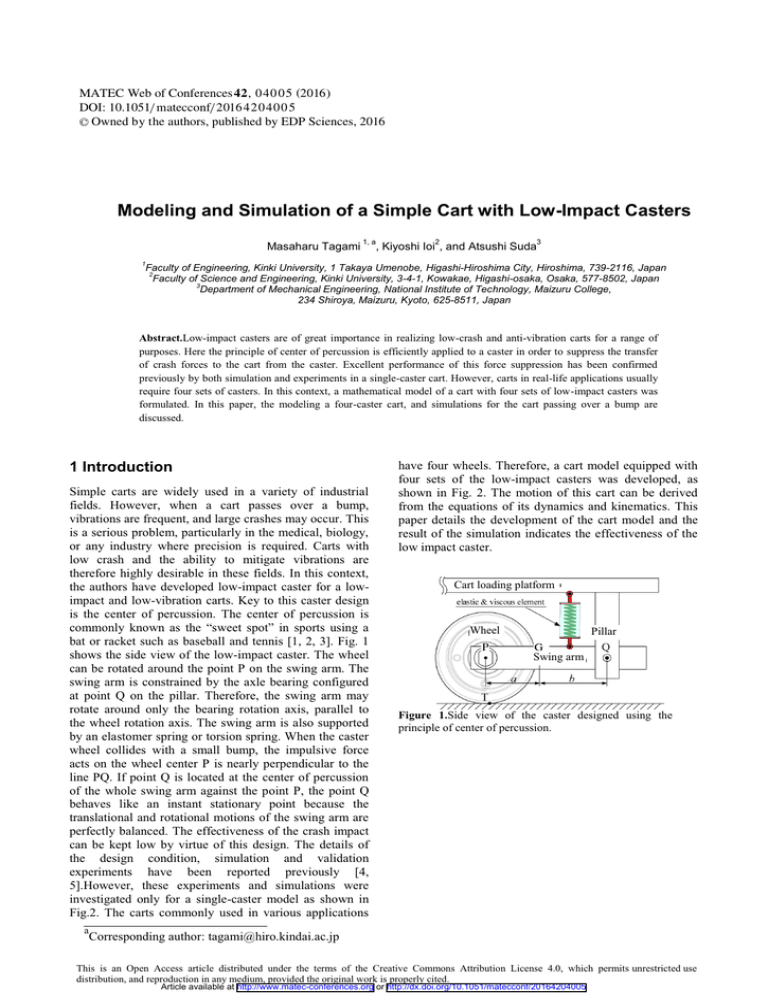
MATEC Web of Conferences 4 2 , 0 4 0 0 5 (2016 ) DOI: 10.1051/ m atecconf/ 2016 4 2 0 4 0 0 5 C Owned by the authors, published by EDP Sciences, 2016 Modeling and Simulation of a Simple Cart with Low-Impact Casters Masaharu Tagami 1, a 2 , Kiyoshi Ioi , and Atsushi Suda 3 1 Faculty of Engineering, Kinki University, 1 Takaya Umenobe, Higashi-Hiroshima City, Hiroshima, 739-2116, Japan 2 Faculty of Science and Engineering, Kinki University, 3-4-1, Kowakae, Higashi-osaka, Osaka, 577-8502, Japan 3 Department of Mechanical Engineering, National Institute of Technology, Maizuru College, 234 Shiroya, Maizuru, Kyoto, 625-8511, Japan Abstract.Low-impact casters are of great importance in realizing low-crash and anti-vibration carts for a range of purposes. Here the principle of center of percussion is efficiently applied to a caster in order to suppress the transfer of crash forces to the cart from the caster. Excellent performance of this force suppression has been confirmed previously by both simulation and experiments in a single-caster cart. However, carts in real-life applications usually require four sets of casters. In this context, a mathematical model of a cart with four sets of low-impact casters was formulated. In this paper, the modeling a four-caster cart, and simulations for the cart passing over a bump are discussed. 1 Introduction Simple carts are widely used in a variety of industrial fields. However, when a cart passes over a bump, vibrations are frequent, and large crashes may occur. This is a serious problem, particularly in the medical, biology, or any industry where precision is required. Carts with low crash and the ability to mitigate vibrations are therefore highly desirable in these fields. In this context, the authors have developed low-impact caster for a lowimpact and low-vibration carts. Key to this caster design is the center of percussion. The center of percussion is commonly known as the “sweet spot” in sports using a bat or racket such as baseball and tennis [1, 2, 3]. Fig. 1 shows the side view of the low-impact caster. The wheel can be rotated around the point P on the swing arm. The swing arm is constrained by the axle bearing configured at point Q on the pillar. Therefore, the swing arm may rotate around only the bearing rotation axis, parallel to the wheel rotation axis. The swing arm is also supported by an elastomer spring or torsion spring. When the caster wheel collides with a small bump, the impulsive force acts on the wheel center P is nearly perpendicular to the line PQ. If point Q is located at the center of percussion of the whole swing arm against the point P, the point Q behaves like an instant stationary point because the translational and rotational motions of the swing arm are perfectly balanced. The effectiveness of the crash impact can be kept low by virtue of this design. The details of the design condition, simulation and validation experiments have been reported previously [4, 5].However, these experiments and simulations were investigated only for a single-caster model as shown in Fig.2. The carts commonly used in various applications a have four wheels. Therefore, a cart model equipped with four sets of the low-impact casters was developed, as shown in Fig. 2. The motion of this cart can be derived from the equations of its dynamics and kinematics. This paper details the development of the cart model and the result of the simulation indicates the effectiveness of the low impact caster. Cart loading platform Wheel Pillar Swing arm Figure 1.Side view of the caster designed using the principle of center of percussion. Corresponding author: tagami@hiro.kindai.ac.jp This is an Open Access article distributed under the terms of the Creative Commons Attribution License 4.0, which permits XQUHVWULFWHGXVH distribution, and reproduction in any medium, provided the original work is properly cited. Article available at http://www.matec-conferences.org or http://dx.doi.org/10.1051/matecconf/20164204005 MATEC Web of Conferences is the position vector from to the working point of the road disturbance force , and are the constraint force and moment of the revolute joint, respectively, and are the masses of the loading platform and the swing arm, respectively, and and are the inertia moments of the loading platform and the swing arm about their centers of gravity. Additionally, an accented tilde is used to indicate the skew-symmetric matrix of an arbitrary vector ∈ R : Figure 2.A cart with single low-impact caster used in previous experiments and a cart withfour sets of low-impact casters of the same design. 0 ≡ " #$ −#% −#$ 0 #& #% −#& ' , = [#& 0 #% #$ ]( . (1) Right rear 䠄i=4䠅 Loading Platform 2 Definitions of Symbols and Coordinate Systems Fig. 3 shows physical model of the cart equipped with four sets of low-impact casters for analysis. The following three right-handed Cartesian coordinate systems were used in this model. − , , is the road coordinate system. This coordinate system is fixed to the road, where the -axis is perpendicular to the plane of the road. − , , is the cart loading platform coordinate system. It is fixed to the cart loading platform, where the origin is placed at the center of gravity of the loading platform. The -axis is parallel to the wheel axle and the -axis is perpendicular to the loading platform. − , , is the swing arm coordinate system. It is fixed to the -th swing arm, and its origin is placed at the center of gravity of the swing arm. The axis is parallel to the wheel axle and the -axis is parallel to the longitudinal direction of the swing arm. Components of the vectors used in this model can be expressed in any of these coordinate systems. denotes that components of the vector are expressed in the coordinate system . The transformation matrix transforms the coordinates of vector from to . The following symbols are used in this model: is the position vector from to the loading platform’s center of gravity, , are the translational velocity and the angular velocity of the loading platform respectively, is the position vector from to the -th swing arm’s center of gravity, , are the translational velocity and the angular velocity of the -th swing arm respectively, is the rotational angle between the pillar and the -th swing arm ( is illustrated in Fig. 3), is the position vector from to the swing arm’s rotational support point, is the position vector from to the swing arm’s rotational support point, Left rear 䠄i=3䠅 Right front䠄i=1䠅 Left front䠄i=2䠅 Swing arm Wheel Figure 3. Physical model of the cart equipped with four sets of low-impact casters. Disk wheel Road View A Road Line of the intersection View A ΔWi Figure 4.Road-wheel contact and the deformation of the wheel rubber. 3 Modeling of the Cart The model cart consists of a loading platform and four sets of low-impact casters as shown in Fig. 3. In this model, the following assumptions were made: x x x the wheel was considered as a part of the swing arm, the effects of wheel rotation were neglected, the pillar that supports the swing arm is fully fixed to the cart platform. anḋ are given by differentiating and with respect to time. The orientation of the cart loading 04005-p.2 ICCMA 2015 platform was expressed by the Euler parameters * .The coordinate transformation matrix that transforms the coordinates of a vector from to can be obtained from * [6].According to the kinematic constraints, can be formulated as follows: = + − . and ̇ are derived by differentiating with respect to time respectively: = − + , (2) and (3) - . ̇ + (4) Because the swing arm is constrained to the loading platform by the axel bearing joint, the angular velocity vector of the swing arm is formulated as follows: = + 1 , (5) where 1 = [̇ 0 0]2 is the relative angular velocity between the loading platform and the swing arm. The angular acceleration of the swing arm may be thus derived by differentiating with respect to time: ̇ = ̇ + ( - 1 The equation of the translational and rotational motion of the cart’s loading platform is given as follows by using Newton’s second law and Euler’s equation: (7) - = − ∑567 + ̇ + ∑567 (8 − ∑567 . (8) Here, and maintain the kinematic constraints between the loading platform and the -thswing arm. (8 is the reaction torque generated by the torsion spring placed parallel to the axle bearing. The torsion spring compensates for the weight of the loading platform and its payload. The equations of the translational and rotational motion of the -th swing arm are obtained similarly: ̇ = + + 3, <:; = B A B<CAD E BA B<CAD E . (11) can be = <F <? , (12) where <F ≡ [0 0 1]( . :1 and :; are under the homothetic relationship. From view A in Fig. 4, homothetic ratio H is given as H = :1 /:; , where :1 and :; are the -axis components of point J: and :; respectively. Coordinate of point J: can be obtained from kinematics.Based on the above discussion, 9: can be formulated as follows: 9: = :; − :1 = :; − α :; = (1 − H)>: <:; . + ̇1 .(6) ̇ = 3 − ∑567 , From the similar geometrical relationship, foumulated as follows: - + ̇ = ̇ − ̇ − also requires its velocity. 9: can be obtained by calculating :; − :1 . :; is equal to the product of unit vector <:; and the wheel radus >: .Unit vector <:; is perpendicular to both <? and . <? is unit vector parallel to the -axis, and @ is the parallel to the intersectional line of the road and the disk wheel. Therefore <:; can be formulatedas follow: (13) Therefore, elastic force N that generates the wheel rubber stiffness is fomulated as follows: ( 9: , N = O: (14) where O: is the stiffness matrix expressed in Σ coordinate system. Viscos force that generates the wheel rubber viscosity is obtaiend by the product of viscosity matrix : and the velocity at the wheel-road contact point. The velocity at that pointis obtained as follows: ( - 1 . + = Because is parallel to the fomulated as follows: ( (15) <:; , = <:; : <:; . is (16) The reaction force is given by the sum of N and .By applying above kinematic relationships to Equations (7)-(10), the final motion equation is obtained as follows: (9) - ̇ + ( = + + − (8 . (10) The reaction force caused by the wheel-road contact was modeled as the viscoelastic force of the wheel rubber. Fig. 4 illustrates the wheel-road contact and the deformation of the wheel rubber. In the formulation of the wheel-road contact, the wheel was considered as a thin disk with a normal vector along the wheel axis. In addition, the wheel-road contact was formulated as onepoint contact. The vector 9: shown in Fig. 4 expresses the maximum deformation and the formulation of QS̈ = , S̈ ≡ [̇ (17) ̇ ̈7 ̈U ̈ ̈5 ]2 , (18) where Q ∈ >7V×7V is inertia matrix, ∈ >7V is composed of the external force and torque, gravity force, Coriolis force and centrifugal force. 4 Simulation 04005-p.3 MATEC Web of Conferences x x x x x The mass and size of the cart are 10.47kg and 400mm width, 600mm depth, 127.5mm height. The initial velocity and orientation of the cart are 0 m/s and parallel to the road (see also Fig. 2). The collision forces from bumps are assumed as pulsed forces at all road-wheel contact points. The width, magnitude and direction of each pulsed force is 50ms, 50N and parallel to -axis. Value W, the length between the center of gravity of the swing arm and the swing arm support point (see also Fig. 1), was varied for the evaluation. 䢴 䣜䢢䣣䣺䣫䣵䢢䣣䣥䣥䣧䣮䣧䣴䣣䣶䣫䣱䣰䢢䣱䣨䢢䣶䣪䣧䢢䣥䣣䣴䣶䢢䢪䣯䢱䣵 䢫 Effectiveness of the low-impact caster was evaluated by the z-axial acceleration of the cart platform. The pulsed force was input at 8second. Fig. 5 and Fig. 6 are the simulation results. Fig. 5 shows the response from 7.9 second to 8.4 second. Fig. 6 is the magnified view of the circle A in Fig. 5. Five values W , 0.1W , 0.2W , 0.5W , 1.5W were applied as W. Here W uniquely satisfies the condition of center of percussion. Fig. 6 indicates that the instantaneous acceleration at 8 second becomes minimum in the case of W = W . From these results, effectiveness of the low-impact caster was confirmed. 䢴䢷䢲 䢴䢲䢲 䢳䢷䢲 䢳䢲䢲 䣒䣵䣧䣷䣦䣱䢢䣫䣯䣲䣣䣥䣶䢢䣨䣱䣴䣥䣧 䢪䢷䢲䣐䢱䢷䢲䣯䣵䢢䣲䣷䣮䣵䣧䣦䢢䣨䣱䣴䣥䣧䢫 䣤䣅䣑䣒 䢢 䢲䢰䢷䣤䣅䣑䣒 䢲䢰䢴䣤䣅䣑䣒 䢲䢰䢳䣤䣅䣑䣒 䢲䢰䢲䢷䣤䣅䣑䣒 䢳䢰䢷䣤䣅䣑䣒 䣋䣯䣲䣣䣥䣶䢢䣨䣱䣴䣥䣧 䢯䢷䢲䢢 䢹䢰䢻 䣃 䢺 䢺䢰䢳 䢺䢰䢴 䣖䣫䣯䣧䢢䢪䣵䢫 䢺䢰䢵 䢺䢰䢶 Figure 5.Simulation result about the z-axial acceleration of the cart platform. 䢸䢲 䢢 䢷䢲 䣒䣵䣧䣷䣦䣱䢢䣫䣯䣲䣣䣥䣶䢢䣨䣱䣴䣥䣧 䢪䢷䢲䣐䢱䢷䢲䣯䣵䢢䣲䣷䣮䣵䣧䣦䢢䣨䣱䣴䣥䣧䢫 䢶䢲 䢵䢲 䢴䢲 䣤䣅䣑䣒 䢲䢰䢷䣤䣅䣑䣒 䢲䢰䢴䣤䣅䣑䣒 䢲䢰䢳䣤䣅䣑䣒 䢲䢰䢲䢷䣤䣅䣑䣒 䢳䢰䢷䣤䣅䣑䣒 䣋䣯䣲䣣䣥䣶䢢䣨䣱䣴䣥䣧 䢳䢲 䢲 䢯䢳䢲䢢 䢹䢰䢻䢻䢻䢷 䢺 䢺䢰䢲䢲䢲䢷 䢺䢰䢲䢲䢳 䣖䣫䣯䣧䢢䢪䣵䢫 䢺䢰䢲䢲䢳䢷 䢺䢰䢲䢲䢴 Figure 6.The instantaneous response to the input of impact force. (Magnified view of the part "A" shown in Fig.5.) 5 Conclusions Simple carts capable of low-impact and low-vibration are highly desirable in many industrial fields. In this context, the authors have developed a low-impact caster based on the center of percussion. Previously experiments using a single low-impact caster proved successful.As a next step, the authors have focused on modeling and simulation of a cart equipped with four sets of low-impact casters. As shown in Fig. 5 and Fig. 6, low-impact caser isolates the impact caused by the bump collision. Upcoming phases of this research are to run simulations under the more practical conditions and to prepare the cart equipped with four sets of low-impact casters for the validation experiments. References 䢷䢲 䢲 䣜䢢䣣䣺䣫䣵䢢䣣䣥䣥䣧䣮䣧䣴䣣䣶䣫䣱䣰䢢䣱䣨䢢䣶䣪䣧䢢䣥䣣䣴䣶䢢䢪䣯䢱䣵䢴䢫 Cart motion simulator was implemented by using MATLAB/Simulink. In the simulation, firstly S̈ inEq. (17) was solved, and subsequently the positions and orientationswere obtained via time integral and kinematics. The purpose of this simulation is to confirm the effectiveness of the low-impact caster and the validity of the simulation results. Consequently, the following simple conditions were applied: 1. Rod Cross, Center of percussion of hand-held implements, American Association of Physics Teachers, Volume 72, No. 5, 2004, pp.622-630. 2.Wen Shi, Yuanbiao Zhang, Tao Zhang and Jianshun Li, Baojun Shi, Modeling and Simulation of Baseball Sweet Spot, Advanced Materials Research, Vol. 156-157, 2011, pp.1635-1638. 3.Hiroyuki K., Takeshi Y., Hideaki N., Shigeto I., Yujiro K., Masaya T. and Kazutaka S., Development of the Evaluating System on Hitting Performance and Choice of Clamping Methods for Baseball Bats, Trans. of JSME (in Japanese), Vol. 77, No.783, 2011, pp.4218-4227. 4. A. Suda, K. Moriya, K. Ioi and M. Yamamoto, Study on a Wheeled Caster for Design of LowCrash Wagons, Transaction of JSME (in Japanese), Vol. 77, No.777, 2011, pp.1998-2007. 5. K. Ioi, T. Kawabuchi, A. Suda, and K. Moriya, Mechanical and Control Design of Caster for Low 04005-p.4 ICCMA 2015 Vibrations and Crashes of Carts, IEEE ICMA proceedings, 2011, pp.1688-1693. 6. Ahmed A. Shabana, Dynamics of Multibody Systems Third edition, Cambridge University Press, 2005, pp.143. 04005-p.5
