Implemen ting T olman's
advertisement
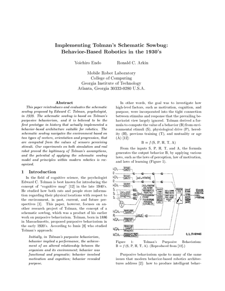
Implementing Tolman's Schematic Sowbug: Behavior-Based Robotics in the 1930's Yoichiro Endo Ronald C. Arkin Mobile Robot Laboratory College of Computing Georgia Institute of Technology Atlanta, Georgia 30332-0280 U.S.A. Abstract This paper reintroduces and evaluates the schematic sowbug proposed by Edward C. Tolman, psychologist, in 1939. The schematic sowbug is based on Tolman's purposive behaviorism, and it is believed to be the rst prototype in history that actually implemented a behavior-based architecture suitable for robotics. The schematic sowbug navigates the environment based on two types of vectors, orientation and progression, that are computed from the values of sensors perceiving stimuli. Our experiments on both simulation and real robot proved the legitimacy of Tolman's assumptions, and the potential of applying the schematic sowbug model and principles within modern robotics is recognized. 1 In other words, the goal was to investigate how high-level factors, such as motivation, cognition, and purpose, were incorporated into the tight connection between stimulus and response that the prevailing behaviorist view largely ignored. Tolman derived a formula to compute the value of a behavior (B) from environmental stimuli (S), physiological drive (P), heredity (H), previous training (T), and mutuality or age (A) [12]: B = f (S, P, H, T, A) From the inputs S, P, H, T, and A, the formula generates the output behavior B, by applying various laws, such as the laws of perception, law of motivation, and laws of learning (Figure 1). Introduction In the eld of cognitive science, the psychologist Edward C. Tolman is best known for introducing the concept of \cognitive map" [12] in the late 1940's. He studied how both rats and people store information regarding their physical locations with respect to the environment, in past, current, and future perspectives [1]. This paper, however, focuses on another research project of Tolman, the concept of a schematic sowbug, which was a product of his earlier work on purposive behaviorism. Tolman, born in 1886 in Massachusetts, proposed purposive behaviorism in the early 1920's. According to Innis [8] who studied Tolman's approach: Initially, in Tolman's purposive behaviorism, behavior implied a performance, the achievement of an altered relationship between the organism and its environment; behavior was functional and pragmatic; behavior involved motivation and cognition; behavior revealed purpose. Figure 1: Tolman's Purposive Behaviorism: B = f (S, P, H, T, A). (Reproduced from [12].) Purposive behaviorism spoke to many of the same issues that modern behavior-based robotics architectures address [2]: how to produce intelligent behav- ior from multiple concurrent and parallel sensorimotor (behavioral) pathways, how to coordinate their outputs meaningfully, how to introduce the notion of goal-oriented behavior, how to include motivation and emotion, and how to permit stages of developmental growth to inuence behavior. is also determined by a specic Orientation Need (a little column rising up from the stippled area). This stippled area is referred to as the Orientation Tensions. The Orientation Need is a product of the Orientation Tension, where the level of Orientation Tension corresponds to the degree of the motivational demand. For example, if the stimulus is a food object, Orientation Tension is determined by the degree of the sowbug's hunger. Moreover, it is assumed that if the sowbug is facing directly toward the stimulus, the Orientation Need decreases. 1.1 Tolman's Schematics Sowbug Model Based on his purposive behaviorism, Tolman proposed the concept of the schematic sowbug (Figure 2) in 1939. The schematic sowbug consists of various unique features that are explained in detail in [11]. The following are brief descriptions of these features, summarized from Tolman's writings: Figure 2: Tolman's Schematic Sowbug. (Reproduced from [12].) Receptor Organ Orientation Orientation Vector Progression Distribution, Hypothesis, and Orientation : The Orientation Distribution, shown as a line graph drawn inside the front-half of the sowbug, indicates the output values of the photo-sensors. The height of each node in the graph is the value of the corresponding photo-sensor in the Receptor Organ. For example, if there is a light source (or any given stimulus) on the left-hand side of the sowbug (as shown in Figure 2), the nodes on the left-hand side of the graph become higher than the ones on the right-hand side. The height of the nodes : The Progression Distribution is also shown as a line graph drawn inside the rear-half of the sowbug. The shape of the Progression Distribution is proportional to the shape of the Orientation Distribution. However, the height of the Progression Distribution is determined by the strength (or certainty) of a specic Hypothesis. For example, if the sowbug is reacting to a food stimulus, the level of Hypothesis is how much the sowbug believes \this stimulus source is really food." The level of a Hypothesis becomes higher the more the sowbug assumes that the stimulus is indeed food. A Hypothesis is a product of the Progression Tensions and the past experience relative to this specic stimulus. Progression Tensions : The Receptor Organ is a set of multiple photo-sensors that perceive light (or any given stimuli) in the environment. These sensors are physically mounted on the front end surface of the sowbug, forming an arc. An individual sensor outputs a value based on the intensity of the stimuli. Distribution, : The vectors pointing at the sides of the sowbug are the Orientation Vectors. The length of the right-hand side vector is the total sum of the left-hand side Orientation Distribution, and the length of the left-hand side vector is the total sum of the right-hand side Orientation Distribution. When an Orientation Vector is generated, the sowbug will rotate toward the direction it is pointing. For example, if there is only a right-hand side vector pointing towards the left, the sowbug will try to rotate in a counter-clockwise direction. If there are two vectors pointing toward each other, the net value (after summation) will be the direction the sowbug will try to rotate. The Orientation Vector will not cause translational movement of the sowbug, only rotational. Need, and Orientation Tensions : Progression Vectors are located at the rear-end corners, left and right, of the sowbug, pointing toward the front. These vectors represent the velocities of the left-hand side and right-hand side motors of the sowbug, respectively. As for Orientation Vector, the length Progression Vector of the left-hand side Progression Vector is determined by the right-hand side of Progression Distribution, and the length of the right-hand side Progression Vector is determined by the left-hand side of Progression Distribution. In other words, if there is a stimulus on the left-hand side of the sowbug, it will generate a larger right-hand side vector, and try to move forward while turning to the left, similar to the notion described decades later by Braitenberg [4]. However, if the sowbug sustains negative experiences regarding the stimulus, the hypothesis then becomes weaker, and it will not move towards the stimulus. The main behavioral characteristic of the schematic sowbug is its positive phototactic behavior. With the combination of the Orientation Vector and Progression Vector, the sowbug is expected to respond to the stimulus in the environment by orienting and moving towards it based on its Orientation Need and Hypothesis. Since both the Orientation Need and Hypothesis are determined by the internal state of the sowbug, which changes as the sowbug increases its experiences with the stimulus, the trajectory of the sowbug is not consistent for dierent trials even if the external conditions are setup same. 1.2 Remarks Tolman acknowledges [11] that his schematic sowbug was inspired by Lewin's \psychological life space" [9] and Loeb's \tropism theory" [10], which was also studied by Blum [3]. Lewin's \psychological life space" indicates \the totality of facts which determine the behavior of an individual at a certain moment." Before Tolman invented the formula which can compute the behavior of animals (i.e., B = f (S, P, H, T, A)), Lewin, a psychologist, attempted to form an equation which outputs the behavior (B) of a person (P) for a given event (E): B = f (P, E) The word \tropism" in Loeb's \tropism theory" describes how plants and low-level organisms try to turn towards a light source. According to Fleming who translated Loeb's work [10], the origin of the word \tropism" comes from a Greek word \trope" for turning. Loeb, a biologist, studied animals' phototactic behavior by trying to gure out how photosensitive substances in animals' bodies undergo chemical alternations by light, and how they would eect the animals' motor behavior [10]. This study let Blum create a model of a phototactic animal by connecting its left-hand side photo-sensors to the right-hand side motor, and right-hand side photo-sensors to the left-hand side motor, and compared it to the statistical results taken from the experiments with cucumber beetles [3]. This again is very similar in spirit to Braitenberg's later descriptions of vehicles exhibiting similar phototactic behaviors [4]. Even though Tolman proposed his system a half-century before Braitenberg did, they were both inspired by Loeb's \tropism theory", and their systems should exhibit similar behaviors. However, Braitenberg's model was implemented with Progression Vectors only, while Tolman's model has both Orientation and Progression Vectors as Blum's model does. From a roboticist's point of view, Tolman's schematic sowbug is remarkable because it was the rst prototype that actually described a behaviorbased robotics architecture in history, to the best of our knowledge. It was a half-century before Brooks developed the subsumption architecture [5] in the mid1980's. However, it should be noted that Tolman's schematic sowbug is not a purely reactive architecture. Past training and internal motivational state will also aect the behavior. 2 Schematic Sowbug Implementation In order to determine the feasibility of actually implementing the schematic sowbug model proposed by Tolman on a physical robot, a C++ program eBug1 (Emulated Sowbug), which runs on RedHat Linux 6.2, was created. eBug emulates the basic features of the schematic sowbug, such as the Orientation Vector, Progression Vector, Orientation Distribution, and Progression Distribution. The program environment can control both a simulated sowbug that reacts to simulated stimuli (Figure 3), and a real robot that reacts to real color objects (Figure 4). The key features of eBug are explained in Section 2.1 and the conguration of the real robot experiment is explained in Section 2.2. 2.1 Key Features of eBug The following key features are implemented in eBug: Stimulus Source: For the simulation mode, the user can place any number of stimuli on the screen, and change their intensities or types by clicking mouse buttons. For the real robot mode, the perceived color objects as seen by the robot are displayed on the screen. Receptor Organ: The nine circles located at the front end surface of the sowbug emulate the 1 The source code is available from http://www.cc.gatech. edu/ai/robot-lab/research/ebug/ . Progression Distribution of the schematic sowbug. The height of each node pP in the graph is a function of the corresponding sensor reading IP and the Hypothesis value H (Equation 4). pP Figure 3: User interface of eBug . properties of the photo-sensors in the schematic sowbug's Receptor Organ. Suppose that the number of the stimuli perceived by the photo-sensor is NS . The intensity reading of the photo-sensor (IP ) is then computed from Equation 1, which takes the intensity of each stimulus (IS ), the angle between the normal of the sensor surface and the rays from the stimulus (P S ), the distance between the sensor and the stimulus (DP S ), and a constant kP as its inputs . IP is assumed to be proportional to the inverse of DP S , and the values for IS and kP are arbitrary assigned. NS 1 IP = kP ISi cos (P Si ) (1) X : The line graph drawn inside the sowbug's body is the Orientation Distribution. The height of each node oP in the graph is a function of the corresponding sensor reading IP and the Orientation Need value O (Equation 2). Moreover, as Tolman assumed, O will be set to be zero if a stimulus is in the direction of the sowbug's heading. oP = IP O (2) Orientation = X NL i=1 oP Li ; VOL = X NR i=1 oP Rj (3) : Another line graph drawn inside the sowbug's body represents the Progression Distribution X NL i=1 pP Li ; VP L = X NR i=1 pP Ri (5) : The sowbug will start reacting to the stimuli when the user clicks on the Run Button in the menu bar. The angular speed ! (counter-clockwise positive) is computed from Equation 6, which takes Orientation Vectors, Progression Vectors, and constants ! and ! . The forward speed v is also computed from averaging the right and left Progression Vectors, and multiplying it with a constant kv (Equation 7). The values for ! , ! , and kv are arbitrary assigned. ! = ! (VOR VOL ) + ! (VP R VP L ) (6) Running Sowbug 0 (VP R + VP L ) (7) 2 The schematic sowbug in eBug can distinguish two dierent types of stimuli, red and green. When these two types of the stimuli are present at the same time, ! and v are calculated independently for each stimulus type, and are summed up at the end to obtain their total values (Equations 8 and 9). !total = !green + !red (8) v Orientation Vector VOR = 0 Distribution : At each side of the sowbug, a set of vectors is pointing towards the sowbug, representing the Orientation Vectors. As shown in Equation 3, the right Orientation Vector value VOR is the total sum of the left-hand-side Orientation Distribution (NL nodes), and the left Orientation Vector value VOL is the total sum of the right-hand side Orientation Distribution (NR nodes). : The vectors pointing to the sowbug from the rear-end represent the Progression Vectors. As it was for the Orientation Vectors, the right Progression Vector value VP R , which is the speed of the right motor, is the total sum of the left-hand-side Progression Distribution, and the left Progression Vector value VP L , which is the speed of the left motor, is the total sum of the right-hand side Progression Distribution (Equation 5). 0 DP Si i=1 (4) Progression Vector VP R = IP H = kv vtotal = vgreen + vred (9) : This window allows the user to directly specify the sowbug's Hypothesis values as well as monitor their changes through the duration of an experiment. Two slider bars indicate the value of the Hypothesis for each of the two colored stimuli, green and red, (labeled \Type-A" and \Type-B", respectively). Hypothesis Window : This window allows the user to monitor the changes in the sowbug's Orientation Need. As in the Hypothesis window, two slider bars indicate the value of the Orientation Need for the two stimuli. Orientation Need Window 2.2 Real Robot Conguration eBug runs not only in simulation but also on a real robot. When it is in the real robot mode, eBug, running on a Dell Precision 410 (Pentium III, 500MHz) desktop computer, remotely communicates with HServer, a component of the MissionLab system [6], running on a Toshiba Libretto 110CT (Mobile Pentium MMX, 233MHz) laptop that sits atop an ActivMedia Pioneer AT robot (Figure 4). HServer is a hardware server that contains drivers for various robots and sensors. After an on-board Sony EVI camera captures the images of the environment, a Newton Cognachrome Vision System [13] processes the images to identify the stimuli (color objects). HServer then sends the data that contain locations of the stimuli to eBug (Figure 5). eBug in return sends the movement commands to the robot via HServer based on the computed values of Orientation Vectors and Progression Vectors. eBug communicates to HServer through IPT [7], and HServer communicates to the robot hardware through serial links. 3 Evaluation 3.1 Simulation Experiment Simulation experiments were conducted to verify the positive phototactic behavior of the sowbug and to investigate how the sowbug's trail changes from both positive and negative experiences with a stimuli. 3.1.1 Setup As shown in Figure 6, two stimuli, green and red, were placed in front of and equally away from the sowbug. Initially, the sowbug's Hypothesis values of both stimuli were set to 50 percent. In other words, with 50 percent uncertainty, the sowbug initially \believes" that the green and red objects are both food objects. Note that the green object is labeled \+" and the red object is labeled \-". If the sowbug eats a positive stimuli, the Hypothesis value increases 10 percent. The Hypothesis value decreases 10 percent if it eats a negative stimuli. This experiment was, therefore, set up to observe how the sowbug learns that the green stimulus is indeed a food. The movement trail of the sowbug was recorded during the eight trials of the experiment. Each trial ends when the sowbug either eats both stimuli or no longer makes any movement. Through the eight trials, the Hypothesis values were not reset by the user, and only altered by the sowbug itself. If the sowbug alters the Hypothesis value after eating a positive or negative stimulus, the value was kept for use in the subsequent trial. At the beginning of each trial, however, the sowbug was relocated to the same initial position, and the two stimuli were placed again at the same exact previous positions with the same positive/negative types. Figure 4: Robot Hardware. Movement Command Object Infomation Figure 6: Schematic sowbug at the initial position in the simulation experiment. eBug 3.1.2 HServer (Hardware Server) Robot Hardware Color Object Figure 5: Information ow for the real robot conguration. Results As can be observed from Figure 7, the simulated schematic sowbug exhibited positive phototactic behavior. Figure 8 shows that the sowbug began to \believe" that the green stimulus is indeed food, and started to \disbelieve" the red stimulus as a food source during the experiment. The captured screen images in Figure 10 show how the Hypothesis values aected the shape of sowbug's trail. In the beginning of the experiment, when the Hypothesis values for the two stimuli were very close, the sowbug approached the stimuli from the center. Later, when the sowbug started discerning that the green stimulus is indeed food, it began to take a path closer to the green stimulus, and when the Hypothesis value of the red stimulus became zero (at the sixth trial), the sowbug no longer approached the red stimulus, even though it oriented itself to the stimuli at the end. 3.2.1 Setup Two stimuli, green and red objects, that were equally distant from the robot's initial position were placed in front of the robot at the beginning of each trial (Figure 9). The Cognachrome Vision System was trained to identify those two colors. In this experiment, however, the Hypothesis values were set manually at the beginning of each trial. Three trials were recorded during the experiment. In the rst trial, the Hypothesis values for both green and red stimuli were 50 percent. In the second trial, the Hypothesis value for the green stimulus was 100 percent and for the red stimulus it was 0 percent. In the third trial. the Hypothesis value for the green stimulus was 0 percent and for the red stimulus it was 100 percent. During this entire experiment, the locations of the color objects were not changed. Figure 7: Screen capture from the simulation experiment. The schematic sowbug is approaching the stimuli during the rst trial. Figure 9: Robot at the initial position in the real robot experiment (top view). 3.2.2 Figure 8: ment. Hypothesis values during the simulation experi- 3.2 Real Robot Experiment In order to determine the potential of the schematic sowbug model for use in the robotics domain, an experiment similar to the one conducted in simulation was also performed on the real robot. Results Captured images in Figure 11 show how the robot performed during the three trials of the experiment. In the rst trial, when the Hypothesis values for both green and red stimuli are 50 percent, the robot chose to approach the red object. In the second trial, when the Hypothesis value for the green stimulus is 100 percent and for the red stimulus is 0 percent, the robot chose to approach the green object. In the third trial, when the Hypothesis value for the green stimulus is 0 percent and for the red stimulus is 100 percent, the robot chose to approach the red object. 4 Conclusion Tolman's schematic model is the rst instance in history, to our knowledge, of a behavior-based model suitable for implementation on a robot. It predates both Brooks' subsumption and Braitenberg's vehicles by approximately a half century. While useful conceptually as a model, it was the goal of this research to test indeed whether or not the model could be implemented on real robots. The primary features of Tolman's schematic sowbug were successfully implemented in both simulation and on a real robot. The results of the simulation experiment were consistent with Tolman's assumption for the sowbug in which he expected to observe its phototactic behavior; when the stimulus was in the eld, the sowbug rotated itself to face the stimulus; and if there was enough belief in the hypothesis, the sowbug moved towards the stimulus. It was also observed that, when the internal state (Hypothesis) of the sowbug is dierent, the sowbug produces dierent trajectories even though the external conditions are set up identically. The results from the real robot experiment proved that it is indeed possible to apply Tolman's schematic sowbug in robotics. Future research could expand the model as currently implemented more completely to draw together more closely psychological models of animal behavior and robotic systems. 5 Acknowledgments The authors would like to thank William C. Halliburton for his assistance on interfacing eBug to the real robot. The Georgia Tech Mobile Robot Laboratory is supported from a variety of sources including DARPA, Honda R&D, C.S. Draper Laboratory, and SAIC. References [1] Anderson, R.E. \Imagery and Spatial Representation." A Companion to Cognitive Science. ed. Bechtel, E. and Graham, G., Blackwell Publishers Inc., 1998, pp. 204-211. [2] Arkin, R.C. Behavior-Based MIT Press, 1998. Robotics. Cambridge, [3] Blum, H.F. \An Analysis of Oriented Movements of Animals in Light Fields." Cold Springs Harbor Symposia on Quantitative Biology. Vol. 3, 1935, pp. 210223. [4] Braitenberg, V. Vehicles: Experiments in Synthetic Psychology. Cambridge, the MIT Press, 1984. [5] Brooks, R. \A Robust Layered Control System for a Mobile Robot." IEEE Journal of Robotics and Automation. Vol. RA-2, No. 1, 1986, pp. 14-23. [6] Endo, Y., MacKenzie, D.C., Stoytchev, A., Halliburton, W.C., Ali., K.A., Balch, T., Cameron, J.M., and Chen, Z. MissionLab: User Manual for MissionLab version 4.0. ed. Arkin, R.C., Georgia Institute of Technology, 2000. [7] Gowdy, J. IPT: An Object Oriented Toolkit for Interprocess Communications - Version 6.4. Carnegie Mellon University, 1996. [8] Innis, N.K. \Edward C. Tolman's Purposive Behaviorism." Handbook of Behaviorism. Academic Press, 1999, pp. 97-117. [9] Lewin, K. Principles of Topological Psychology. trans. Heider, F. and Heider, G.M. McGraw-Hill, New York, 1936. [10] Loeb, J. The Mechanistic Conception of Life. ed. Fleming, D. Cambridge, The Belknap Press of Harvard University Press, 1964. [11] Tolman, E.C. \Prediction of Vicarious Trial and Error by Means of the Schematic Sowbug." Psychological Review. ed. Langfeld, H.S. Vol. 46, 1939, pp. 318-336. [12] Tolman, E.C. Behavior and Psychological Man. University of California Press, 1951. [13] Wright, A., Sargent, R., Witty, C., and Brown, J. Cognachrome Vision System User's Guide. Newton Research Labs, 1996. (a) (b) (c) Figure 10: Screen captures from the simulation experiment: (a) Final position of Trial 1; (b) Final position of Trial 4; (c) Final position of the last trial (Trial 8). (a1) (a2) (a3) (b1) (b2) (b3) (c1) (c2) (c3) Figure 11: Sequence of images from the real robot experiment: (a1) - (a3) Trial 1. The Hypothesis values for both green and red stimuli are 50%; (b2) - (b3) Trial 2. The Hypothesis values for the green stimulus is 100% and for the red stimulus is 0%; (c2) - (c3) Trial 3. The Hypothesis values for the green stimulus is 0% and for the red stimulus is 100%.
