Mutual Inductance & Transformer Circuits with LTspice IV
advertisement

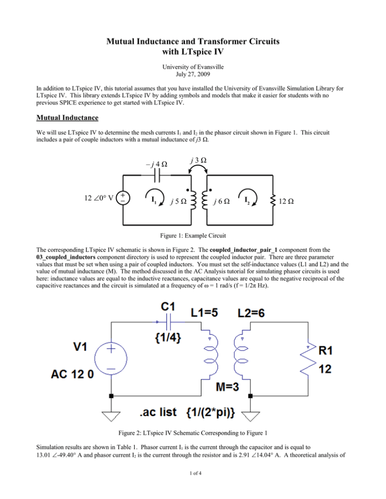
Mutual Inductance and Transformer Circuits with LTspice IV University of Evansville July 27, 2009 In addition to LTspice IV, this tutorial assumes that you have installed the University of Evansville Simulation Library for LTspice IV. This library extends LTspice IV by adding symbols and models that make it easier for students with no previous SPICE experience to get started with LTspice IV. Mutual Inductance We will use LTspice IV to determine the mesh currents I1 and I2 in the phasor circuit shown in Figure 1. This circuit includes a pair of couple inductors with a mutual inductance of j3 Ω. j3Ω –j4Ω 12 ∠0° V + – I1 j5Ω j6Ω I2 12 Ω Figure 1: Example Circuit The corresponding LTspice IV schematic is shown in Figure 2. The coupled_inductor_pair_1 component from the 03_coupled_inductors component directory is used to represent the coupled inductor pair. There are three parameter values that must be set when using a pair of coupled inductors. You must set the self-inductance values (L1 and L2) and the value of mutual inductance (M). The method discussed in the AC Analysis tutorial for simulating phasor circuits is used here: inductance values are equal to the inductive reactances, capacitance values are equal to the negative reciprocal of the capacitive reactances and the circuit is simulated at a frequency of ω = 1 rad/s (f = 1/2π Hz). Figure 2: LTspice IV Schematic Corresponding to Figure 1 Simulation results are shown in Table 1. Phasor current I1 is the current through the capacitor and is equal to 13.01 ∠-49.40° A and phasor current I2 is the current through the resistor and is 2.91 ∠14.04° A. A theoretical analysis of 1 of 4 the circuit gives identical results. Note that LTspice defines the current through a voltage source as positive when entering the positive terminal of the source. The current through V1 is therefore the negative of the current through C1. The negative of a phasor can be obtained by either adding or subtracting 180° from the phase angle (by convention phasor angles are in the range from -180° to +180°, we either add or subtract 180° so that the phase angle of the result is within this range.). frequency: 0.16 Hz I(C1): mag: 13.0158 phase: -49.3987° device_current I(R1): mag: 2.91043 phase: 14.0362° device_current I(V1): mag: 13.0158 phase: 130.601° Table 1: Simulation Results for Figure 2 device_current A second example circuit with a pair of coupled inductors is shown in Figure 3. 5Ω 20 ∠60° V + – I1 j2Ω j3Ω j6Ω I2 –j4Ω Figure 3: A Second Mutual Inductance Example Circuit The corresponding LTspice IV schematic is shown in Figure 4. Note how the inductor pair is oriented and connected so that the “dots” match those in Figure 3. Figure 4: LTspice IV Schematic Corresponding to Figure 3 Simulation results are shown in Table 2. Current I1 is equivalent to current I(R1) and is 3.578 ∠86.565° A. Current I2 is equivalent to current I(C1) and is 5.367 ∠86.565° A. These results agree with those obtained from a theoretical analysis of the circuit. 2 of 4 frequency: 0.16 Hz I(C1): mag: 5.36656 phase: 86.5651° device_current I(R1): mag: 3.57771 phase: 86.5651° device_current I(V1): mag: 3.57771 phase: -93.4349° Table 2: Simulation Results for Figure 4 device_current Linear Transformers Linear transformers are just a special case of a pair of coupled inductors. Separate linear transformer components are available in the UE library, but the underlying model is equivalent to that of a coupled inductor pair. Ideal Transformers The ideal transformer shown in Figure 5 is modeled in the UE library as shown in Figure 6. ip NP : Ns is ip + + + vp vs vp – – – Figure 5: Ideal Transformer Symbol is + + (N /N ) v – s p p (Ns/Np) is vs – Figure 6: UE LTspice IV Ideal Transformer Model A phasor domain ideal transformer circuit is shown in Figure 7. The equivalent LTspice IV schematic is shown in Figure 8. The UE ideal transformer model requires that values for the number of winding turns in the primary and secondary be specified. It is not necessary to specify the actual number of turns, it is only necessary that the ratio of turns be correct. In the schematic shown in Figure 8, NP:NS values of 1:4, 0.25:1, or 2:8 all give identical results. 2Ω 120 ∠0° Vrms 1:4 16 Ω + Vo – + – – j 24 Ω Figure 7: Ideal Transformer Circuit Simulation results are shown in Table 3. There is again excellent agreement with results obtained by theoretical analysis. 3 of 4 Figure 8: LTspice IV Schematic Corresponding to Figure 7 frequency: 0.16 Hz V(vo): mag: 214.663 phase: 116.565° I(C1): mag: 8.94427 phase: -153.435° device_current I(R2): mag: 8.94427 phase: -153.435° device_current I(R1): mag: 35.7771 phase: 26.5651° device_current I(V1): mag: 35.7771 phase: -153.435° Table 3: Simulation Results for Figure 8 device_current 4 of 4 voltage


