Intelligent Cinematography and Editing: Papers from the AAAI-14 Workshop
Robust Locally Weighted Regression for
Aesthetically Pleasing Region-of-Interest Video Generation
Daniel Couturier and Daniel DeTone and Homer Neal
University of Michigan
500 S State St.
Ann Arbor, MI 48109
{dancout, ddetone, haneal} @umich.edu
Abstract
We have developed a system that can use the scattered detector outputs mentioned above to create a smooth, visually
appealing path for the RoI to travel along. We outline basic rules to accomplish this task in section 3.2, and offer a
viable, automated alternative to camera operators with our
smoothing model presented in Section 3.3.
One method for automating the recording of a scene is to use
an object tracker on a stationary video which captures a large
portion of the scene containing the object. The object tracker
attempts to localize the object to be recorded at each time
step. These algorithms focus on minimizing localization error, but fail to address any videography concerns which would
arise from using these trackers to guide sub-video containing
the tracked object, also known as a a Region-of-Interest (RoI)
generated from a larger video. We provide a method that takes
the output from an object tracker and creates a smoothed RoI
to be viewed as the final output video. To accomplish this,
we use a variation of linear regression, namely, robust locally weighted linear regression (rLWLR-Smooth). We evaluate this method on a short, one-minute clip of a speaker giving a talk. We show that our method minimizes jerk while
maintaining the speaker in the visible portion of the video.
1
2
Related Work
There are systems in use today that create aesthetically
pleasing videos for users to watch. However, these systems
involve moving, mechanical parts and therefore present the
possibility of mechanical failure and maintenance problems.
Some of these systems also require that the presenter wear
some form of physical ”identifier”, such as an LED necklace
worn around a speaker’s neck, in order to be recognized by
the tracking system (Vaddio 2014). This system performed
well in controlled environments, but encountered difficulty
in scenes with other infrared light sources such as lamps,
projectors, and stairwell lighting. Additionally, they fail outdoors in the prescence of sunlight.
The most relevant system to our own is ClassX, and was
developed by researchers at Stanford University (Pang et al.
2011b). ClassX provides a framework for Region-of-Interest
(RoI) control within a larger, wide-angle video of a lecture.
ClassX does have a track mode, but it does not consider any
guidelines for creating aesthetically pleasing video. While
the track mode offered does capture important parts of the
lecture, the transitions and motion of the RoI are not polished, as this is not a focus of their work.
As mentioned previously, it is desirable to develop a
system which smoothly moves an RoI in a larger field of
view. To do this, one must first localize the object to be
tracked in the video in each frame. There are many methods
which are capable of tracking objects in color video. A
wide array of tracking techniques is presented in (Yilmaz,
Javed, and Shah 2006). In this work, Yilmez et. al. present a
taxonomy of tracking methods which can be broken down
into three general methods: point tracking, kernel tracking,
and silhouette tracking. In this paper, we chose to focus on
using inputs which fall into the kernel tracking category,
as they are popular and can be applied to a wide variety of
applications. Popular state-of-the-art kernel object trackers
include (Kalal, Mikolajczyk, and Matas 2012), (Babenko,
Yang, and Belongie 2011) and (Grabner and Bischof 2006).
Introduction
Typically, professional camera operators are hired to record
important events in order to produce pleasing video. While
professional camera operators are generally very effective in
creating a pleasing output video, hiring these operators can
become highly expensive over the course of time. We seek to
replicate a human camera operator. One method for accomplishing this task is to generate a portion of a larger frame,
where the larger frame captures all potential object locations
in a scene. State-of-the-art computer vision technology offers systems that can successfully detect targets in a video.
However, the sub-video created by centering the RoI around
the center of each detection is often very unsteady, as described in section 4.
The ”Region-of-Interest” is an important term used in this
paper, and was originally mentioned in (Pang et al. 2011a).
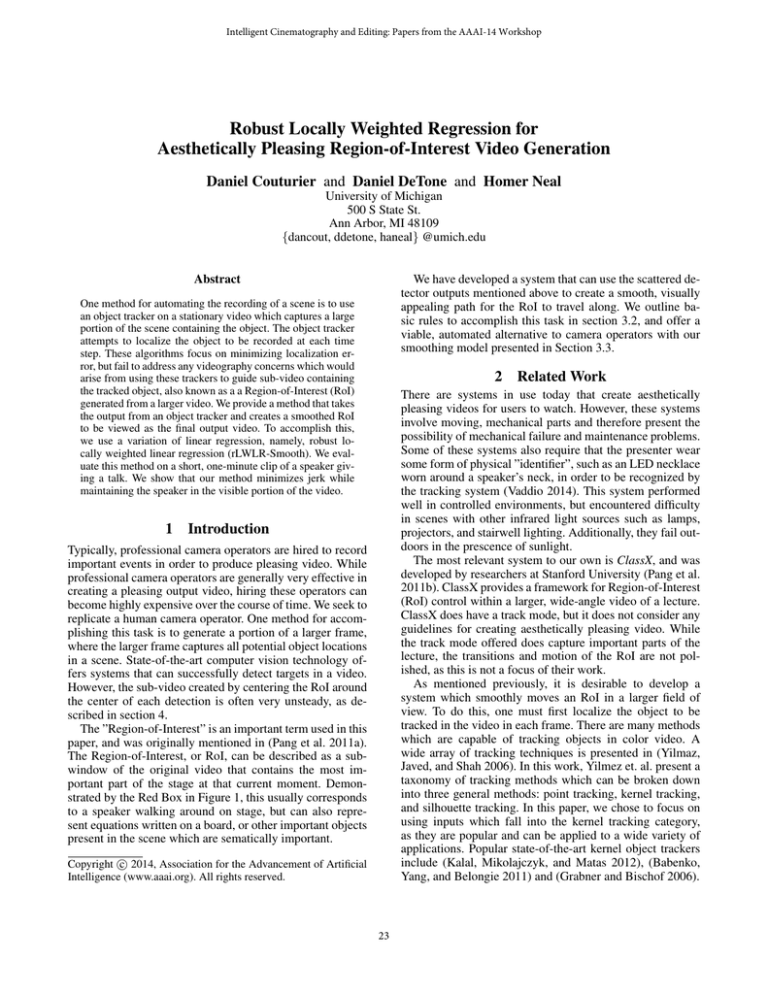
The Region-of-Interest, or RoI, can be described as a subwindow of the original video that contains the most important part of the stage at that current moment. Demonstrated by the Red Box in Figure 1, this usually corresponds
to a speaker walking around on stage, but can also represent equations written on a board, or other important objects
present in the scene which are sematically important.
c 2014, Association for the Advancement of Artificial
Copyright Intelligence (www.aaai.org). All rights reserved.
23
Figure 1: Wide-angle image with RoI bounding box. In this image we show an example of a wide-angle image, capturing a
large stage. The red bounding box represents the boundaries of the RoI.
path of the RoI. In other words, our model has the capability to work with long video sequences. It is possible to
use any state-of-the-art object detector to generate the highconfidence training data needed for our rLWLR model. We
are only interested in high-confidence data so that we can be
sure the detection is accurate. Because of this selectiveness,
the set of detection data has the potential to be sparse in a
sense where we are limited, do not have position data, for all
timestamps over the course of a long video.
Our paper offers the following contributions:
1. We propose a set of reasonable guidelines for creating
aesthetically pleasing video of a presenter from the cropping of a sub-video from a larger video. These are outlined in Section 3.2.
2. We propose a simple method which can be used as a post
processing step for position estimates generated by stateof-the-art object trackers.
3
3.1
3.2
Proposed Method
Method Summary
RoI Motion Guidelines
In order to create an aesthetically pleasing video, we developed a set of guidelines for our system to follow as closely
as possible. These guidelines were developed keeping what
would make a pleasing, easily viewable lecture recorded
video in mind. They are presented as:
Online object trackers, such as (Kalal, Mikolajczyk, and
Matas 2012), (Babenko, Yang, and Belongie 2011) and
(Grabner and Bischof 2006) are able to track arbitrary objects in close to real time. A typical measure of success for
an object tracker is to measure the average pixel error between the center of the track created and the center of the
object at each time step. If one uses the center of the track
created by these trackers as the center of an RoI trajectory
as it moves around a larger video, the resulting video would
be quite jumpy (we verify this in Section 4). This results in
a final video which is quite unpleasant to watch.
To improve the videographic quality of RoI videos produced by online trackers, we propose a method to create a
smoothed, aesthetically pleasing path to drive the trajectory
of an RoI containing an object of interest.
We constrain the problem of smoothing the RoI to the offline setting, meaning all the target position training data is
available during our smoothing calculations. By considering
position estimates from future frames, which is only possible in the offline setting, the RoI can preemptively move
such to maintain a smooth trajectory and still maintain the
speaker in the visible part of the frame. This is much more
difficult in the online setting.
Due to the nature of our locally weighted model, only
points close to the position under inspection will affect the
1. Target must remain in the visible region of a video
2. Minimize camera jerks
Here, the ’visible region’ of a video is the portion of the
sub-window that encompasses the speaker entirely. If the
speaker is not easily viewable in this portion of the subwindow, ignoring occlusions, then the target is not in the
’visible region.’ We can justify this rule knowing that in order to properly track a target, it must be visible for the entire
sequence. Not having a visual on the target is essentially useless while watching a video of that target.
In physics, a jerk, also known a jolt, surge, or lurch, is the
rate of change of acceleration, or, in other words, the rate
of change of acceleration with respect to time. By analyzing
the jerk of the position of the RoI in recorded video, we can
characterize erratic and jumpy behavior of camera control.
Erratic and jumpy behavior in videographic is bad because
it makes it difficult to focus on objects in the field of view.
We briefly evaluate the jerk characteristic of our method in
Section 4.
24
3.3
Robust Locally Weighted Linear Regression
information of the speaker, as shown in Figure 1. Because
the speaker’s motion is primarily along the length of the
stage, we chose to only evaluation his horizontal motion.
The rLWR-Smoothing method can be used similarly for
smoothing vertical motion.
For input to our rLWLR-Smooth algorithm, we chose to
use the Track-Learn-Detect algorithm by Kalal et. al. (Kalal,
Mikolajczyk, and Matas 2012) as it generalizes well to many
applications and has recently acheived state-of-the-art performance. To intialize the tracker, we specifed a bounding
box around the face of the speaker. Although the face undergoes many pose variations, it remains relatively unoccluded
which can be a major problem for online kernel trackers.
In our experiment, we first normalize the input data in
both the frame number dimension (x-axis in Figure 2a) and
horizontal tracker center position (y-axis in Figure 2a) by
subtracting the mean and dividing by the standard deviation.
This helps to improve numerical stability and, in the case of
the horizontal tracker center, allow the parameters to generalize across different motion characteristics corresponding
to different speaker trajectories. For the kernel width, we
chose τ = 0.1. Additionally, input data which was assigned
a weight less than = 0.01 were rounded to zero to improve efficiency. For the parameter in the bi-square weighting function, we chose k = 1. This means that tracker positions which are more than one standard deviation away from
the previous smoothed location were assigned zero weight
in the residual weighting function. Lastly, we chose M = 3
as our polynomial order. All the aforementioned parameters
were chosen empirically.
We now analyze Figure 2. In 2a, we show the trajectory
produced by both the tracker and our rLWLR-Smooth algorithm. Around frame 690, one can observe a major jerk in
the tracker trajectory, due to tracker error. This largely uneffects the smooth trajectory produced by our algorithm. In
2b, we plot the pixel error of the tracker center and the RoI
center versus the ground truth data of the video sequence.
For aesthetically pleasing video, as specified by 1, we require that the target remain visible in the video frame. As
shown in 2b, the maximum error induced by the smoothing algorithm is 75 pixels, which means that the center of
the speaker remains approximately in the middle 50% of the
RoI, thus satisfying guideline 1. Figure 2c, plots the velocity
of raw tracker output and the smoothed output against frame
number. The jerk around frame 690 is apparent. Lastly, we
plot the absolute value of the jerk of both the raw tracker
output and the smoothed output. Note the order of magnitude difference of the y-axis labels. In the smoothed figure
2d, the jerk around frame 690 is indistinguishable. The magnitude of the smoothed absolute jerk is reduced by more than
an order of a magnitude from the raw tracker, thus we have
greatly reduced jerk, as specified by 2.
To smooth the erratic behavior of object position localized
by online kernel tracking methods, we propose to use a regression algorithm which we call Robust Locally Weighted
Linear Regression (rLWLR-Smooth). At the core of our
method in linear regression. In linear regression, one minimizes the following objective function:
X
(t(i) − wT φ(x(i) ))2
(1)
i
In this equation t represents the target values which we
aim to fit our function to. In the case of smoothing an RoI
trajectory, t represents the position of the object as given by
the object tracker. x represents the input data. In our case, it
is the frame number. φ(•) represents a basis function that is
applied to x. In our method, we use a polynomial function of
order M . w is a vector of M + 1 dimensional weights which
we wish to solve for to minimize equation 1.
To deal with potentially long video input, we turn to locally weighted linear regression (LWLR). LWLR considers
a neighborhood of nearby x values and iterates through the
data from the first frame to the last to solve for w. LWLR
instead minimizes the following objective function:
X
r(i) (t(i) − wT φ(x(i) ))2
(2)
i
We introduce the term r(i) which adds a weight to nearby
x values, depending on their distance from the query point,
x(i) . The following is a standard choice for r(i) and closely
mimics the Gaussian distribution:
(i)
x − x2
(i)
r = exp(−
)
(3)
2τ 2
Finally, to deal with situations where tracker error results
in major outliers (as in frame 690 in Figure 2), we introduce
a second weighting function. This second weighting function is the weighting function typically associated with the
bi-square robust M-estimator. Thus, we apply this second
function to help remove outliers:
[1 − ( ke )2 ]2 for |e| ≤ k
f (n) =
(4)
0
for |e| > k
4
Evaluation
In this section, we briefly evaluate the degree to which the
method described in Section 3 improves the aesthetic quality
of an RoI centered on raw tracker output to capture a tracked
object. Namely, we aim to measure this improvement in relative quality in terms of 1 and 2 from Section 3.2.
We evaluate our Robust Locally Weighted Linear Regression Smoothing (rLWLR-Smooth) algorithm on a short sequence of 1400 frames (approximately one minute). In this
short sequence, a speaker on a stage is recorded as he moves
horizontally on the stage. The video resolution is 2080 x 580
pixels and is taken from a stationary color camera placed
in the rear of the lecture hall. We chose a RoI size of 250
x 400. This RoI size does a good job of capturing detail
References
Babenko, B.; Yang, M.-H.; and Belongie, S. 2011. Visual tracking with online multiple instance learning. IEEE
Transactions on Pattern Analysis and Machine Intelligence
(PAMI).
25
Grabner, H., and Bischof, H. 2006. On-line boosting and
vision. In Proceedings of the 2006 IEEE Computer Society Conference on Computer Vision and Pattern Recognition
- Volume 1, CVPR ’06, 260–267. Washington, DC, USA:
IEEE Computer Society.
Kalal, Z.; Mikolajczyk, K.; and Matas, J. 2012. Trackinglearning-detection. IEEE Transactions on Pattern Analysis
and Machine Intelligence 34(7):1409–1422.
Pang, D.; Halawa, S.; Cheung, N.-M.; and Girod, B. 2011a.
Mobile interactive region-of-interest video streaming with
crowd-driven prefetching. In Proceedings of the 2011 International ACM Workshop on Interactive Multimedia on Mobile and Portable Devices, IMMPD ’11, 7–12. New York,
NY, USA: ACM.
Pang, D.; Halawa, S. A.; Cheung, N.-M.; and Girod, B.
2011b. Classx mobile: region-of-interest video streaming
to mobile devices with multi-touch interaction. In Candan
et al. (2011b), 787–788.
Vaddio. 2014. Autotrak 2.0 with hd-20 camera.
Yilmaz, A.; Javed, O.; and Shah, M. 2006. Object tracking:
A survey. ACM Comput. Surv. 38(4).
26
(a) RoI Position
(b) RoI Pixel Error
(c) RoI Velocity
(d) RoI Jerk
Figure 2: In each of the above figures, output from raw tracker data is plotted in red, while output from our algorithm (rLWLRSmooth) is plotted in blue. In each figure, the frame number is plotted on the x-axis. In Figure A, we plot the horizontal position
of each RoI path. The up and down motion is caused by the speaker moving back and forth across the stage. In Figure B, we
show pixel error. In Figure C, the velocity, and in Figure D the jerk. Jerk is the derivative of acceleration with respect to time.
Note the difference in scale in Figure D.
27

