Proceedings of the Twenty-Second Innovative Applications of Artificial Intelligence Conference (IAAI-10)
A Sketch Recognition System for Recognizing
Free-Hand Course of Action Diagrams
T. Hammond, D. Logsdon, B. Paulson, J. Johnston, J. Peschel, A. Wolin, and P. Taele
Sketch Recognition Lab, Department of Computer Science and Engineering
Texas A&M University, College Station, TX 77840, srl@tamu.edu
Abstract
attempts to apply sketch recognition to COAs have resulted
in systems that can only recognize a handful of shapes, often
require users to draw each shape with a specific gesture, and
do not allow users to draw freely (Pittman et al. 1996).
In this paper, we present a first-look at an application that
allows military commanders to hand-draw hundreds of COA
symbols directly on a digitized map. The number of symbols
we support is vastly greater than previous sketch recognition
interfaces, and, by utilizing many artificial intelligence techniques, our system can rank the correct interpretation in the
top three returned results 89.9% of the time, for 485 symbols.
Military course-of-action (COA) diagrams are used to depict
battle scenarios and include thousands of unique symbols,
complete with additional textual and designator modifiers.
We have created a real-time sketch recognition interface that
recognizes 485 freely-drawn military course-of-action symbols. When the variations (not allowable by other systems)
are factored in, our system is several orders of magnitude
larger than the next biggest system. On 5,900 hand-drawn
symbols, the system achieves an accuracy of 90% when considering the top 3 interpretations and requiring every aspect
of the shape (variations, text, symbol, location, orientation)
to be correct.
Implementation and Methodolgy
Introduction
The flowchart in Figure 1 shows the steps we take to recognize drawn course of action symbols. The following sections
explain the recognition steps in more detail.
Drawing with pen and paper is a common method for users
to convey visual information. Sketch recognition seeks to
harness the power of pen and paper by automatically understanding freehand-sketched input with a stylus and digitizing
screen. Furthermore, sketch recognition attempts to recognize the intent of the user while allowing the user to draw in
an unconstrained manner. This permits the user not having
to spend time being trained how to draw on the system, nor
will the system need to be trained on how to recognize each
users particular drawing style.
The recognition of hand drawings has a variety of uses, including symbol recognition in Computer-Aided Design systems, providing automatic correction or understanding of
diagrams for immediate feedback in educational settings,
functioning as alternative inputs for small keyboard-less devices (such as Palm Pilots), or providing gestural interfaces.
Our aim as sketch recognition researchers is to build systems
using artificial intelligence techniques that recognize drawndiagrams with human-recognizer efficiency and accuracy.
One real-world domain that has thousands of symbols is
military course of action (COA) diagrams. Military commanders use COA diagrams to plan field operations, where
the symbols represent troops, supplies, obstacles, and movement patterns. Currently, commanders draw COAs by hand
on a map for planning purposes, and then these diagrams are
entered into a computer through typical WIMP interfaces for
purposes of simulation and plan communication. Previous
Grouping
In our framework, we have recognizers that work well for
shapes and some that work well for text and decision graphics. PaleoSketch is used to recognize basic geometric shapes
like rectangles, lines, and ellipses, while our handwriting
recognizer (HWR) is responsible for recognizing text, decision graphics, and echelon modifiers. The job of the grouping algorithm is to make sure the right strokes go to the right
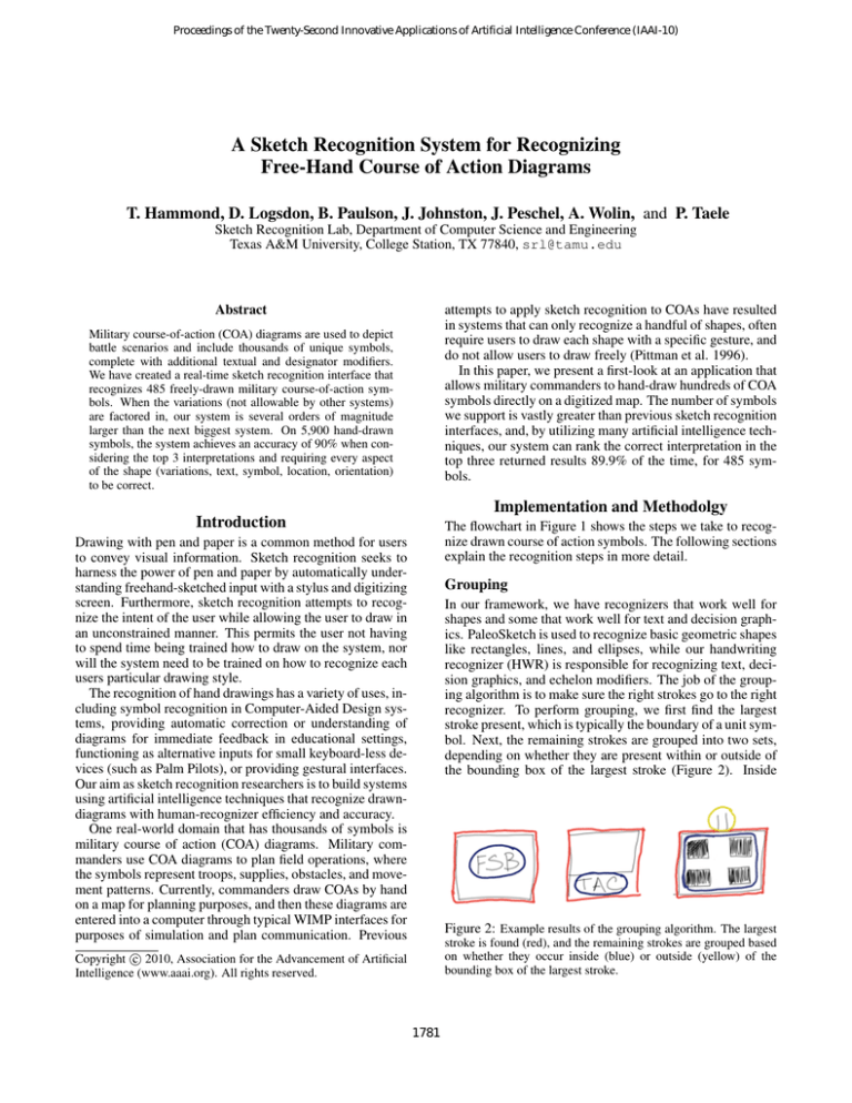
recognizer. To perform grouping, we first find the largest
stroke present, which is typically the boundary of a unit symbol. Next, the remaining strokes are grouped into two sets,
depending on whether they are present within or outside of
the bounding box of the largest stroke (Figure 2). Inside
Figure 2: Example results of the grouping algorithm. The largest
stroke is found (red), and the remaining strokes are grouped based
on whether they occur inside (blue) or outside (yellow) of the
bounding box of the largest stroke.
c 2010, Association for the Advancement of Artificial
Copyright Intelligence (www.aaai.org). All rights reserved.
1781
Figure 1: The recognition process, starting from a stroke represented in an XML datafile, to the final, unique symbol identifiers, SIDCs.
strokes are either going to be decision graphics, text, or type
modifiers that need to be sent to the primitive recognizer.
These strokes are initially run through the HWR and if the
returned confidence is high enough, they are marked as text
or decision graphics. If the confidence is low, then they are
sent to PaleoSketch to be recognized as primitive shapes.
Strokes that occur outside of the bounding box of the largest
stroke are typically echelon modifiers and can recognized by
the HWR.
Segmentation
Figure 3: Primitive shapes supported by our modified version of
Stroke segmentation involves breaking drawn strokes into a
set of primitive building blocks, such as lines or arcs. In our
system, we split every drawn stroke into a series of lines.
These polyline representations of the stroke are then sent
into our primitive recognizer, PaleoSketch.
We use a combination of multiple algorithms in order to produce a highly accurate polyline segmentation
(Wolin, Paulson, and Hammond 2010; Wolin, Eoff, and
Hammond 2008; Wolin, Paulson, and Hammond 2009;
Sezgin, Stahovich, and Davis 2001; Kim and Kim 2006;
Douglas and Peucker 1973).
PaleoSketch.
Dashed Primitives
Many symbols in the COA domain are “anticipated” and
drawn with dashed boundaries containing an arbitrary number of lines. To search for dashed boundaries, we start by
first finding instances of dashed lines. The algorithm starts
by iteratively cycling through the shapes on the screen in
temporal order and maintaining a stack of lines (and dots)
that make up a possible candidate for a dashed line. As
we encounter conditions that indicate a dashed shape is not
present (e.g. large slope change, large gap between strokes),
the stack is sent to a function that generates a dashed line if
it contains more than one shape. Once all dashed lines have
been found, they are placed into four different bins based
on their orientation: those that are close to vertical (within
15 degrees), close to horizontal, or have a positive or negative slope. Next, we search within the horizontal and vertical
bins for possible rectangles, and within the positive and negative bins for diamonds. For dashed ellipses, we perform a
similar operation to that of dashed lines, except that we also
Primitive Recognition
The goal of primitive recognizers is to classify individual
strokes into one of a set of basic building block shapes.
These primitive shapes can then be combined to form more
complex symbols using high-level shape grammars like
LADDER (Hammond and Davis 2005). For primitive recognition, we use an extended version of the PaleoSketch algorithm (Paulson and Hammond 2008). This version of PaleoSketch supports 13 different primitive shapes, which can
be seen in Figure 3.
1782
allow for polylines are arcs to be considered as dashes. Once
we have a stack of candidate dashes for an ellipse, we generate a temporary stroke using the endpoints and midpoints of
the strokes on the stack. If this generated stroke passes conditions of an ellipse test, then we group the strokes together
as a dashed shape.
Figure 4: LEFT: Sketch of a mechanized infantry unit. The con-
Decision Point Recognition
straints for this symbol dictate that the two diagonal lines that
form the X (the infantry part) are coincident with the respective corners of the rectangle, and that one of the lines has a
positiveSlope and the other a negativeSlope. The ellipse (the mechanized part) must be contained within the rectangle,
and all the centers must be roughly coincident with each other.
RIGHT: Sketch of a mechanized infantry unit with various modifiers. After our recognition algorithms determine there is a rectangle in the sketch, it can group strokes according to contextual
placement relative to the rectangle. The two Xs above the rectangle belong to the unit’s echelon, the minus to the right tells us that
the unit is reduced, and the alphanumeric identifier at the lower left
helps us identify this particular unit. Without the context of the
recognized rectangle, identifying these other pieces of information
(especially differentiating the echelon X from the X in the center
of the rectangle) can become difficult.
Decision points are typically drawn as 10-line stars in COA
diagrams. Stars are searched for using a similar approach to
dashed shapes. However, in addition to checking the spatial
distances between consecutive strokes, we also verify that
the angles between lines alternates between acute and obtuse
angles.
Handwriting Recognition
The handwriting recognizer uses two pre-built multi-layer
perceptron models from Weka to recognize inner and echelon text, respectively. Echelon text comprises of the symbols
‘x’, ‘+’, ‘-’, ‘1’, and ‘*’. Inner text has the character set A-Z
and 0-9, with some special symbols used in decision graphics (See DecisionGraphics). When strokes are passed to the
handwriting recognizer, they are first grouped to combine
the strokes into logical words and characters based on the
stroke’s spatial separation and overlap, and using the left-toright assumptions of handwriting.
After these stroke groupings are formed, a brute-force approach is taken to compute the character and word possibilities. Our domain has no word more than seven letters, and
each character is no more than five strokes, so the number
of possible words is bounded. A confidence value for each
possible character or word is computed using the multi-layer
perceptrons, and the handwriting with the best confidence
value is used for further symbol recognition.
Figure 5: Examples of phase lines and boundary lines. On the left,
a Phase Line, ‘PL’, is uniquely identified by the identifier, ‘BLUE’.
On the top-right, an ambiguous phase or boundary line is drawn
horizontally. On the bottom-right, a Boundary Line is labeled with
a company echelon, ‘II’, and the unique identifiers ‘1-2’ and ‘4-5’.
CALVIN
CALVIN is a heuristic-driven geometric recognizer based
on LADDER (Hammond and Davis 2005). It builds complex high-level shapes by combining shapes (primitves recognized by PaleoSketch (Paulson and Hammond 2008) or
other high-level shapes) in different combinations. The ways
that shapes can be combined are dictated by geometric constraints, such as saying that one shape contains another, or
that the endpoints of two lines are coincident. As an example, see Figure 4 LEFT, a sketch of a mechanized infantry
unit. Some of constraints that might be used to specify how
the parts of this shape fit together include the lines having a
positiveSlope and negativeSlopve, as well as the
endpoints being coincident with the corners of the rectangle.
In addition to the basic recognition capabilities found in
LADDER, CALVIN has been hand-tuned using heuristics to
increase the accuracy and efficiency of recognizing course of
action diagrams. It re-analyzes the set of shapes for grouping purposes. Although strokes have already been grouped
for recognition at earlier stages, recognition context can help
us re-group strokes more accurately. For instance, if the
primitive recognizer has detected a rectangle with a high
degree of confidence, then we can say that certain strokes
in certain positions relative to that rectangle should go together. After grouping, it is then able to accurately put together the requisite pieces of a military symbol. In Figure 4
RIGHT, we show the same sketched unit except with modifiers. Once CALVIN determines a rectangle has been drawn,
we use contextual rules to determine the inner portions of the
symbol (the X and ellipse), and the different outer portions
of the symbol. In this case, the user has drawn an echelon
(the two Xs on top), noted that the unit is reduced (the minus on the right), and assigned an identifier (in the lower
left) to the unit. Without contextual rules, identifying all
these components simultaneously becomes an NP-complete
search problem.
Phase/Boundary Lines
Phase lines and boundary lines define the location steps of
military operations and the boundaries by which military
units are confined, respectively (Figure 5). Phase and bound-
1783
Interface
In producing our COA interface, we have identified three
requirements: quick creation, simplicity, and readability.
First, we must design this interface in such a way that
course of action maps can be quickly created. The interface
is critical because this project is intended to be used in a
critical environment under time constraints. Indeed, a major
goal of this project is to speed up creation of course of action
maps, so its interface should facilitate this requirement. All
of the recognizers reported above supply confidence values,
the interface uses these to order the different results.
Second, we require simplicity. Sketch recognition, by
definition, aims to simplify the user experience by allowing all or most user input in the form of sketching. This
implies that our application could be extremely simple, perhaps consisting of only a drawing surface and a handful of
buttons.
Finally, readability is our third requirement. The sketch
recognition algorithm produces a list of interpretations ordered by probability. Usually, the desired shape is returned
at the beginning of the list. However, when dealing with a
large set of possible shapes, the desired interpretation may
in fact be second or third in the list. We therefore have to
display a few top recognition results in a way that keeps the
interface simple and usable. We feel that we have successfully incorporated these requirements into the interface.
To fulfill our requirements, our interface consists of a
drawing panel and a few toolbar buttons. We provide quick
creation and simplicity by including few interface elements,
allowing immediate creation upon launching, and automatically performing recognition and displaying results. Also,
after a shape is drawn by the user, recognition automatically
occurs when the hand is removed from the screen. To facilitate our readability requirement, the top results are displayed
in panels once recognition finishes. These panels display
textual information about the possible symbols as well as
a preview image. We have displayed this information in a
manner that is easily readable. While these core requirements have been implemented, we have added a few more
features to enhance the creation process.
We have included a few intelligent features that help improve the user experience. First, we have included stroke
beautification (Figure 7). This occurs on two levels. In
many symbols, a user’s strokes are replaced by a correct
symbol image file. Some symbols, however, are defined
by user-drawn boundaries and, therefore, do not have image files associated with them. Many of these amorphous
shapes contain some text labels which are written in by the
user. Our interface uses handwriting recognition to convert
handwriting into text while keeping the user-defined boundary in these types of shapes. In addition to stroke beautification, we have included a set of basic editing tools including move, duplicate, and delete. These tools, while simple,
provide some much needed functionality. We have also implemented a fourth tool to convert a beautified symbol to its
user-drawn strokes and back again. This obviously helps us
in testing our application, but it also can help users understand the sketch recognition process.
Figure 6: On the left, we have a General Belt obstacle symbol.
On the right is a Minefield Static obstacle. These obstacles can be
drawn with dynamic patterns, such as with more or less spikes for
the General Belt, or more inner circles in the Minefield Static.
ary lines can be arbitrary contours, and they are recognized
first by determining if there is a long stroke of sufficient
length. If a long stroke exists, then the remaining strokes
are assumed to be text and are sent to the handwriting recognizer. The handwriting recognizer looks for type identifiers,
such as ‘PL’ or ‘BL’, and unique identifiers, such as ‘BLUE’
or ‘ALPHA’ that could distinguish the phase and boundary
lines.
Areas
Areas are large, closed strokes that mark zones of interest,
such as the landing zones (‘LZ’) shown in the penultimate
step of the flowchart (Figure 1). The area recognizer first
determines if the largest stroke in the symbol is closed. If a
large, closed stroke exists, then echelon, type identifier, and
unique identifier text is looked for. Echelons are located at
either the top or bottom of the closed stroke, and identifier
text is located inside of enclosure.
Decision Graphics
Decision graphics are type modifiers that include a combination of filled and un-filled rectangles and triangles. Because
the primitive recognizer is not equipped to handle filled-in
shapes, we recognize these symbols using the HWR. These
shapes are included in the common dictionary that handles
modifiers that occur within the bounding box of the largest
shape on the screen (as determined by the grouper). If the
HWR detects instances of decision graphic modifiers, it then
analyzes all shape definitions that are of the type “DecisionGraphic” to find the correct symbol.
Obstacles
Some course of action shapes are drawn using similar drawing patterns, yet can contain a dynamic number of pattern
repetitions (Figure 6). These symbols can be recognized by
looking at the symbols on a micro-level. A set of features
are computed for each symbol, and this “bag of features” is
compared to a set of template patterns. Symbols with similar
patterns can then be recognized.
Arrows
Arrows indicate movement of friendly or hostile forces and
are allowed to have arbitrary paths. We recognize arrows
by looking at the number of strokes drawn, the number of
line segments the strokes can be broken into, and the type of
arrow head used.
1784
(a) The user drew COA symbols in our interface using a stylus.
(b) Drawn symbols are beautified, where some of the symbols are
replaced with their recognized images, and the text becomes typed.
Figure 7: Our interface incorporates stroke beautification, which takes recognized strokes (7(a)) and turns them into cleaned images (7(b)).
Results and Discussion
multimodal system utilizing a multi-agent architecture that
can be applied for a number of applications. One such
application was an interface for inputting course of action
shapes was LeatherNet, an interface that requires users to
use a combination of speech and sketch input for drawing
the shapes. The multimodal input activates an over-theshelf speech recognizer, as well as a traditional pen-based
gesture recognizer consisting of a neural network and hidden Markov models, whenever the user places the pen on
screen. The system therefore listens to both speech and gesture simultaneously during interface usage. While QuickSet demonstrated that it can complete the task faster than
existing CAD-style interfaces at the time (Forbus, Usher,
and Chapman 2003), the necessity of speech as a modality
for users using the system to describe the layout of forces
in simulated exercises using course of action shapes have
exhibited shortcomings. Specifically, even current speech
systems are severely limited in noisy environments, and target users of such a system have repeated reported that they
would not use it if it has a speech recognition requirement
(Forbus, Usher, and Chapman 2003), which is the case for
the QuickSet system.
We trained our recognizers on a set of 485 different symbols, collecting over 6,000 samples drawn by researchers
and course of action diagram experts. We tested on a different set of data consisting of 5,900 samples drawn by 8 researchers (not that none of these users were included in the
data used for the development and training of the system).
We return multiple interpretations for each symbol recognized, since many of the symbols are often similar with only
minor nuances. The correct interpretation is returned as the
top result 84.4% of the time, in the top three results 89.9% of
the time, and in the top ten results 90.8% of the time. These
recognition results are on par with current sketch recognition
systems, and they are phenomenal when considering that we
have an order of magnitude more symbols than other applications support.
We have not conducted large-scale user interface evaluations at this time or deployed our interface with military experts, but we hope to do so in future research. A video of the current system is posted here:
http://srlweb.cs.tamu.edu/srlng/research/project/22
Related and Prior Work
nuSketch Battlespace Interface
Frameworks and systems have been created that either can
specified to handle sketched course of action shapes, or provide alternative implementations in doing so. We discuss
such works and discuss their limitations that have been improved upon by our implementation.
The nuSketch Battle Interface (Forbus, Usher, and Chapman 2003) is a more recent system for handling sketched
course of action shapes, and was designed to address the
shortcomings of systems such as QuickSet. The first notable contrast of the nuSketch approach to previous systems
is its focus on sketching and the lack of a speech modality. Despite the systems heavy emphasis on sketching for
drawing up battle plans, the sketch-based interface does not
utilize recognition on the users input. Instead, the system
QuickSet System
An early system that was used for battle plans involving
course of action shapes was QuickSet (Cohen et al. 1997), a
1785
Acknowledgments
relies on visual and conceptual understanding of the input to
drive the drawing up of battle plans using sketched course
of action shapes, and relies more on reasoning techniques of
the sketched shapes themselves. In order to address the lack
of recognition techniques, the system also depends heavily
on interface mainstays such as toolbars, combo boxes, and
type-in boxes to facilitate inputting the sketches.
The authors would like to acknowledge Christine Alvarado,
Paul Corey, Daniel Dixon, Brian Eoff, Marty Field, Robert
Graham, Brandon Kaster, Walter Moriera, Manoj Prasad,
Pat Robinson, Cassandra Rutherford, Metin Sezgin, and
Yuxiang Zhu, in their participation in and discussion of the
ideas of this work. This work is supports in part by NSF
grants 0757557 and 0744150.
LADDER framework
References
One framework that has served as the basis to our work is
the LADDER framework (Hammond and Davis 2005), a
domain-independent sketching language that can be used to
describe how shapes and shape groups are drawn, edited,
and displayed in the recognition process. The language is
used as a tool to describe higher level symbols as a combination of lower-level primitives that fulfill certain geometric
constraints, and is useful for recognizing symbols in a domain absent of domain-specific information. Examples of
domains that have successfully utilized LADDER include
biology, music notation, East Asian characters and sketchbased educational games. A limitation of LADDER though
is that it does not handle symbols that are difficult to describe geometrically or are ambiguous without context, as is
the case with many course of action shapes.
Cohen, P. R.; Johnston, M.; McGee, D.; Oviatt, S.; Pittman, J.;
Smith, I.; Chen, L.; and Clow, J. 1997. Quickset: multimodal
interaction for simulation set-up and control. In Proceedings of the
fifth conference on Applied natural language processing, 20–24.
Morristown, NJ, USA: Association for Computational Linguistics.
Douglas, D., and Peucker, T. 1973. Algorithms for the reduction of
the number of points required to represent a digitized line or its caricature. Cartographica: The International Journal for Geographic
Information and Geovisualization 10(2):112–122.
Forbus, K. D.; Usher, J.; and Chapman, V. 2003. Sketching for
military courses of action diagrams. In IUI ’03: Proceedings of the
8th international conference on Intelligent user interfaces, 61–68.
New York, NY, USA: ACM.
Hammond, T., and Davis, R. 2005. LADDER, a sketching
language for user interface developers. Computers & Graphics
29(4):518–532.
Kim, D., and Kim, M.-J. 2006. A curvature estimation for pen
input segmentation in sketch-based modeling. In Computer-Aided
Design, 238–248.
Paulson, B., and Hammond, T. 2008. PaleoSketch: Accurate primitive sketch recognition and beautification. In Proceedings of the
13th International Conference on Intelligent User Interfaces (IUI),
1–10. New York, NY, USA: ACM.
Pittman, J. A.; Smith, I. A.; Cohen, P. R.; Oviatt, S. L.; and Yang,
T. C. 1996. Quickset: A multimodal interface for military simulation. In Sixth Conference on Computer-Generated Forces and
Behavioral Representation.
Sezgin, T. M.; Stahovich, T.; and Davis, R. 2001. Sketch based
interfaces: Early processing for sketch understanding. Workshop
on Perceptive User Interfaces.
Stolt, K. 2007. Sketch recognition for course of action diagrams. Master’s thesis, Massachusetts Institute of Technology,
Cambridge, MA.
Wolin, A.; Eoff, B.; and Hammond, T. 2008. Shortstraw: A simple
and effective corner finder for polylines. In Eurographics 5th Annual Workshop on Sketch-Based Interfaces and Modeling, 33–40.
Wolin, A.; Paulson, B.; and Hammond, T. 2009. Sort, merge, repeat: an algorithm for effectively finding corners in hand-sketched
strokes. In SBIM ’09: Proceedings of the 6th Eurographics Symposium on Sketch-Based Interfaces and Modeling, 93–99. New York,
NY, USA: ACM.
Wolin, A.; Paulson, B.; and Hammond, T. 2010. Combining corners from multiple segmenters. In Submission.
COA Design Interface
The COA Design Interface is a system that addresses the
limitations of LADDER for sketched course of action shapes
by extending that frameworks capabilities (Stolt 2007). Besides modifying LADDER to make it domain-specific to
sketched course of action shapes, one significant extension
is the use of the Intermediate Feature Recognizer (IFR). This
recognizer serves multiple purposes such as recognizing certain shapes (e.g., variably-drawn) not handled by LADDER
well, as well as provide error correction. The IFR allows a
larger variety of shapes to be handled with reasonable accuracy, and thus is capable of reporting up to 247 shapes.
The current implementation is still lacking components that
are critical to military planners drawing battle plans, such as
course of action shapes that contain text.
Conclusion
This paper describes a sketch recognition system that recognizes military course of action diagrams. The sketch recognition system recognizes 485 different military course-ofaction diagram symbols, with each shape containing its own
elaborate set of text labels and other variations. Even without the variations and text this is well over an order of magnitude more symbols than the next largest system. When one
factors in the variations (not allowable by other systems),
this system is several orders of magnitude larger than the
next biggest system. On 5,900 student hand-drawn symbols,
the system achieves an accuracy of 90-percent when considering the top 3 interpretations and require every aspect of
the shape (variations, text, symbol, location, orientation) to
be correct.
1786

