Challenges in Semantics for Computer-Aided Designs:
A Position Paper
William Regli and Joseph Kopena
Drexel University
Philadelphia, PA 19104, USA
• Content-based retrieval of 3D CAD models based on their
manufacturing processes, functional attributes and shape
semantics.
Abstract
This paper presents a brief summary of a number of different approaches to the semantic representation and automated
interpretation of engineering data. In this context, engineering data is represented as Computer-Aided Design (CAD)
files, 3D models or assemblies. Representing and reasoning
about these objects is a highly interdisciplinary problem, requiring techniques that can handle the complex interactions
and data types that occur in the engineering domain. This paper presents several examples, taken from different problem
areas that have occupied engineering and computer science
researchers over the past 15 years. Many of the issues raised
by these problems remain open, and the experience of past
efforts can serve to identify fertile opportunities for investigation today.
• Representation and indexing of the structure, function and
behavior of CAD assemblies (entire products or electromechanical systems).
• The representation and extraction of design process and
rationale.
• Representation of digital engineering design information
for long-term archival.
Examples from the authors’ body of work is provided in
each case to illustrate some of the fundamental problems and
to provide a context for describing the current open challenges in the semantic representation and automated interpretation of 3D Computer-Aided Design representations of
engineering data.
Introduction
The relationships among shape and form, structure and function, and behavior and semantics are among the most fundamental questions studied by science and engineering—and
it is precisely these relationships that must be captured and
preserved by digital engineering artifacts. Engineering artifacts, such buildings, aerospace and automotive products,
and consumer goods are nearly ubiquitously represented in
digital form as 3D Computer-Aided Design (CAD) models
in commercial CAD systems. In spite of the fact that nearly
every object we use in modern life has its genesis as a digital
representation in a CAD system, we understand surprisingly
little about the explicit semantics of these objects. As a result, even after over 40 years of development of digital engineering tools, their use remains largely as a proxy for paper
drawings and the semantic content of the objects they create remains locked in the cognitive processes of engineering
team.
This paper presents a brief introduction to five separate, but highly related, problems in representation and capture of the semantics of engineering artifacts produced by
Computer-Aided Design. Specifically,
• The conversion of 3D CAD models into manufacturing features to generate instructions for Computer-Aided
Manufacturing (CAM).
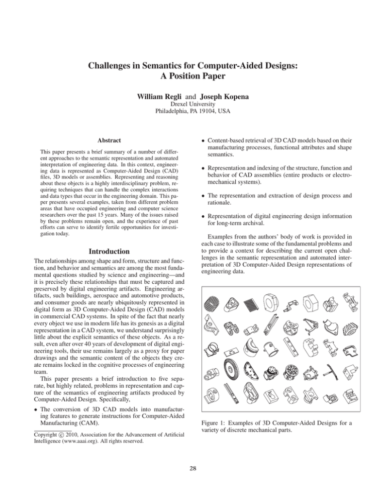
Figure 1: Examples of 3D Computer-Aided Designs for a
variety of discrete mechanical parts.
c 2010, Association for the Advancement of Artificial
Copyright Intelligence (www.aaai.org). All rights reserved.
28
“holes” that serve as mating features to attach the part to
another part in an assembly model. The holes are modeled
geometrically as a subtractive operation or a swept contour;
they may have associated with them attributes such as manufacturing tolerances (i.e., cocentricity or circularity) that describe how tightly the final artifact must match the mathematical shape.
In contrast, manufacturing features are specific to the
manufacturing process to be used to create the artifact. In
the case of the “socket”, the object is to be machined from
a cylindrical block of metal (Figure 2 (a.c)) and the “machining features” correspond to the metal cutting operations
needed to remove the material in the delta-volume (Figure 2
(a.d)). These features are shown in Figure 2 (b) and are
vastly different from those used in design. For example, machining features must take into account the geometry of the
cutting tool, as well as the robotic motion that the machining
center is capable of. These features correspond to the possible volumes swept by a rotating cutting tool undergoing 2.5
axis motion. For the socket, there are 22 possible machining
features—these can be used to produce up to 512 possible
process plans (i.e., sequences of cutting operations). While
only a few of these process plans make manufacturing sense,
the interpretation of the shape in terms of all of its possible
manufacturing steps is a key challenge in developing automated manufacturing planning tools.
55
30
40
20
30
30
50
100
200
(a)
The Semantics Problems. Recognizing features from a
design is the means of providing a level of design understanding to manufacturing software systems. Beyond
just manufacturing features, the problem of feature recognition is really one of mapping between different interpretations of a shape in different contexts. For example, feature
recognition is a key algorithmic element in CAD translation software—in which CAD data is transformed between
different file formats and internal representations. Unlike a
word processing document (whose principal internal structure is some form of text markup), CAD representations are
often generative. A generative representation uses a set of
features to create a procedural definition of a shape. Further
complicating matters, each CAD system uses a different set
of design features and operations, thus the generative representations vary widely across commercial systems.
Many researchers have looked into these problems. They
are a key part of efforts in the ISO 10303 STEP standard.
However the pace of change in the commercial world greatly
outstrips standard’s progress and we find ourselves perpetually in a situation where substantial human effort is required
to extract the design intention from one model and map it
into alternative representations. There currently exist no
common ontologies of features, nor are there any suitable
“corpa” for use in developing feature taxonomies.
(b)
Figure 2: An example of automated feature extraction: (a) a
design model is interpreted as (b) a set of manufacturing features that correspond to machining operations on a milling
center.
Some Challenge Areas for Engineering
Semantics
Automated Feature Extraction
Feature recognition is a common algorithm in a wide variety of pattern recognition applications (i.e., vision, machining learning, etc). In the context of Computer-Aided Design
and Computer-Aided Manufacturing (CAD/CAM), feature
recognition provides the communication medium between
design data and manufacturing applications. Features also
form a basic component of tools for design analysis and
feedback, as well as for systems that automatically generate process plans and drive manufacturing processes.
What is particularly devilish for engineering is that there
are a multitude of different feature representations depending on what point one it at in the design lifecycle. For example, a designer may work with design features (shown in
Figure 2 (a.a)). Design features typically are operations on
the 3D models to create shape attributes with functional or
behavioral properties. In the example, a “socket” part has
Content-based Retrieval of CAD Objects
Since the early 1970s, researchers have been interested in
automating the indexing and retrieval of engineering objects stored in databases. There are two basic types of approach for matching and retrieval of 3D CAD data: (1)
29
Prismatic-Machined Parts
?1
C as t
Ma nufa c turing
Ma c hine d
Functional
Brackets
Cast-then-Machined Parts
?2
H
Housings
K
−
+
(b)
(a)
Figure 3: An example of CAD artifacts (a) with different manufacturing interpretations and (b) a shape-based discriminator for
distinguishing among these manufacturing processes.
feature-based techniques and (2) shape-based techniques.
The feature-based techniques are the oldest. They are based
on extracting engineering features e.g., machining features,
and form features, from a solid model of a mechanical part
for use in database storage, and automated coding. These
techniques often work off of the native CAD or solid model.
These models are mathematically precise, topologically watertight, and algorithmically and numerically complex. For
example, solid model might consist of a data structure describing the boundary of a 3D model in terms of a set of
NURBS patches. Interrogating and reasoning about the information in this model requires understanding the semantics of the underlying geometric and topological representations.
The Semantics Problems. In the CAD/CAM domain, engineering artifacts can have multiple classifications. For example, discrete machined parts can be classified in to different categories according to different classification criteria, such a functionality (e.g., brackets or fasteners), manufacturing cost and manufacturing process (e.g., casting, machining, forging, molding). Figure 3 (a) shows four CAD
models under two different, but perfectly reasonably, classification schemas. The first classification is based on the
manufacturing process, where parts are separated into either
“3-axis machining” or “casting” processes. In machining,
rotating cutting tools remove material based on swept volumes; these sweeps are limited to those on a 3-axis vertical
machining center. The second, orthogonal classification, is
based on mechanical function. Figure 3 (a) also shows a
decomposition into parts that function as “brackets” or as
“housings”.
The shape-based techniques are more recent, owing to
research contributions from computational geometry, computer vision, and computer graphics. A shape-based approach works as the representational “lowest common denominator”: polygon mesh available from faceting solid
models, in the form of VRML or STL. From the polygon
mesh, different transformation invariant attributed can be extracted as the means of similarity among 3D models. In contrast to the CAD and solid model techniques, the semantics
of VRML and STL and other mesh formats is trivial. However, along with this simplicity comes a severe loss of the
design knowledge present in the native geometry as well as
loss in the accuracy of the shape models themselves.
Representation of Structure, Function and
Behavior
In order to tackle the many abstract concepts and underlying structures involved, effective reasoning on mechanical assemblies requires knowledge-based mechanisms for
representing the design intent for the assembly. Assemblies are primarily defined by their intended function—goals
achieved and tasks performed—and the decomposition of
that function into sub-functions. These in turn define form,
structure, and behavior. It is therefore the representation and
reasoning of function to which this work has been initially
scoped. Reasoning at this abstract, design rationale-oriented
level is best accomplished through the application of knowledge representation and reasoning techniques. Doing so under a framework with clear semantics, desirable for auto-
Shape matching techniques are generally robust under
model degradation, but it is a rigid technique and is a poor
discriminator among model classes, because it usually emphasizes gross model shape, rather than the discriminatory
features that are common in CAD/CAM data.
30
mated reasoning, entails formal logic.
The example shown in Figure 4 gives a representation
based on function and flow—the materials, energies, and
signals on which functions operate. The representation is
broken up into two parts: a core ontology, defining the basic structure of a function-based mechanism description language, and vocabulary extensions, providing terminologies
with which rich descriptions can be written in the language.
The core ontology defines the universe of objects as consisting of assemblies, components, functions, and flows. Several relations are also given, for example to associate assemblies with functions and functions with their input and output flows. The vocabulary extensions provide taxonomies of
functions and flows derived from those developed in prior
work by the authors and colleagues at NIST.
Beyond the representation of structure, function and behavior is design rationale. Design rationale is an explanation
of why an artifact, or some part of it, is designed the way
it is. Design rationale includes all the background knowledge such as deliberating, reasoning, trade-off and decisionmaking in the design process of an artifact—information
that can be valuable, even critical, to various people who
deal with the artifact. The research has ranged from basic observations about the design process to different approaches to capturing design rationale.
(a)
The Semantics Problems. Current representations for
function and behavior are still largely ad hoc. Is is very difficult to have a representation that rigorously and unambiguously captures the semantics of a mechanism. Complicating
matters is the fact that there can be multiple interpretations
of the function and behavior. In some ways this is not unlike the problems faced in the intelligence, machine vision
or plan recognition domain, where various low-level events
can be consistently described in several ways. Current approaches are to provide languages expressive enough to describe and distinguish devices while maintaining efficiency
and computability. It is neither so formal as to prevent practical computing, nor so informal as to prohibit automated
reasoning. The following section outlines the use of such
reasoning in a design repository.
A second challenge is the integration of these languages
into existing commercial design and manufacturing software systems and workflows. Current CAD/CAM tools
are still predominantly geometry-centric. While various research and even commercial systems have attempted to create “knowledge-based CAD systems”, these have focused
usually on formalizing design rules and less on the representation and capture of design rationale. Automating the
generation of these representations is also difficult.
Windshield
Wiper
Referring
artifact
Sub
Sub_of
Sub
Gear Function
Rotation conversion
Inflow
Outflow
High speed
rotation
Oscillation Function
Motion conversion
Outflow
Rotation Function
Motion conversion
Inflow
Sub
Sub_of
Sub_of
Mechanical
Function
Wiping motion
Inflow
Outflow
Referring
artifact
Source
Destination
Referring
artifact
Low speed
rotation
Low speed
circular
motion
Referring
artifact
Source
Low speed
oscillating
motion
Destination
Shaft
Source
Worm and
Gear pair
Destination
Source
Arm with Peg
Destination
Wiper Arm
Slide Rocker
(b)
Figure 4: An example of a simple mechanical assembly (an
abstraction of a windshield wiper) and a function-flow representation of its behavior.
Long-Term Archiving of Digital Engineering
Artifacts
Perhaps the most significant open problem is that of extraction of engineering semantics in order to ensure long-term
sustainability of engineering artifacts. For many modern industries, engineering design and manufacturing knowledge
needs to be preserved over 50-to-75 year lifespans. Tradi-
31
digital preservation. However, the current STEP standard
does not cover the full breadth of problems needed to ensure
long-term interpretability of engineering knowledge. Issues like organizational workflow, information provenance,
model evolution over time and relationships among model
representations (that may not be in STEP) are all critical to
ensure that future users of this preserved engineering knowledge can understand the data they have access to.
(a) The “live” snake robot.
Drive Motor
Example: Drexel’s Bio-Robotic Snake. Consider the
capture the semantics of a complex design and analysis task
for simulation of the biologically-inspired (snake-like) robot
shown in Figure 5(a). In this example, one of the principal challenges is how to capture and represent the simulation/analysis workflow, shown in Figure 5(c).
Tail
Head
Articulating
Motors
Motor
Segment
The Semantics Problems. Archiving introduces many
new problems in semantics. For example, long-term interpretability is not often a design criteria for knowledge representation structures. Specific to engineering, however, the
workflows, processes and internal complexities of engineering objects all require new ideas for representation. Provenance is particularly troublesome in an engineering context:
models are often passed around an organization, with many
individuals creating derivative models specific for the needs
of their task in the workflows. The result is a family of related models, all of which describe the same artifact. Hence,
to really understand the artifact (i.e., for diagnostic or forensic purposes) one really needs to have access to this network
of files and understand their relationships.
Processor
Segment
(b) A 3D CAD model of the snake robot.
(c) Design and simulation workflow.
Figure 5: CIBER-U Case Study: A Bio-Inspired Robot.
tional digital data management for these organizations are
usually dependent on the proprietary formats of commercial software systems and cannot guarantee the readability
and utility of data over long periods. While 3D computeraided design (CAD) modeling has become an indispensable
aspect of modern engineering, the engineering part print
(i.e., blueprint or 2-D drawing on paper, aperture cards, microfiche) remains as the principal method of design knowledge archival. From an archival standpoint, much of the
knowledge generated during the modern engineering enterprise (i.e., by 3D CAD, simulation, etc.) is simply lost in this
process. Even considering data that are archived, over a long
enough product lifetime, the data files and supporting infrastructure required to access CAD product designs will be obsolete and unusable. Some artifacts (i.e., airframes, ships,
bridges and other civil infrastructure) have lifetimes that extend not just over changes in CAD software packages, but
across the development of CAD and computing technology
technology itself.
One might hold out hope that these problems would be
addressed by either industry or the international standards
community. International standards such as STEP, ISO
103033, are certainly an integral aspect of any solution for
(a) A bestiary of engineering formats.
(b) A cam in solid and mesh format.
Figure 6: Two challenges with engineering objects: the diversity of related file elements and their internal representational complexities.
Discussion and Open Issues
The engineering domain is a rich source of a semantics problems. Across all of the examples above, the complexity
and diversity of engineering data is shown to pose unique
32
challenges. For CAD and 3D data in the engineering process, many derivative model representations must be created
for the various workflows central to design, manufacturing,
and lifecycle activities. For example, some geometric models contain data that specifies shape, but the shape can be
specified in different ways—each with different representational power, precision and end purpose. Shown in Figure 6,
Vertex-based Model data, Curve Models, Wireframe Models, Surface Models, and Solid Models may all exist in the
engineering workflow. Today, the vast majority of objects
produced by modern CAD software are 3D models or solid
models. One of the main the derivative models from 3D
solid models include meshes, (polyhedral approximations of
3D objects, usually used in graphics for rendering). However, the semantic content of a 3D mesh is far lower than
that of the 3D solid model as present in a proprietary CAD
system (i.e., Pro/Engineer). Understanding these trade-offs,
and how to represent and capture these semantics, is largely
a open problem.
Another factor contributing to the complexity of this domain: Engineering artifacts each have a physical realization.
CAD models usually represent a manufacturable object (i.e.,
physical part, building, assembly, etc). Existing approaches
to shape semantics are usually designed for recognition and
classification—rarely venturing into the representations required to understand how to manufacture or assemble the
structure described. For example, a part is machinable on a
3-axis machining center or it is not; a part has four symmetrically spaced holes for fastening with bolts or it does not.
This is in contrast to problems in the domain of information
retrieval, where datasets are pre-classified based mostly on
human intuition (i.e., boats get grouped with boats; airplanes
with airplanes).
Infrastructure Grants OCI-0636273 and OCI-0636235. Any opinions, findings, conclusions or recommendations expressed in this
material are those of the author(s) and do not necessarily reflect the
views of the NSF or the other supporting government and corporate
organizations.
Conclusions
This paper has presented a number of problems related to
the representation of semantics in the context of engineering
artifacts and CAD/CAM data in particular. The engineering
domain is of unique global importance, as it documents our
infrastructure, consumer products and defense and healthcare systems. Given its importance, it is surprising that the
domain has not seen more sustained and large-scale efforts
to comprehensively address the issue of semantics. In many
ways the engineering domain shares considerable similarity with eScience: as engineering activity migrates to exist
nearly entirely on a digital substrate, semantic representations are needed to understand and capture the interactions
among data, software and human elements. These problems
are likely to be perpetual, as with each subsequent generation there are new technologies, design concepts and products we require new structures to capture and represent this
knowledge.
Acknowledgments. This work was supported by the Library of Congress’ National Digital Information Infrastructure
and Preservation Program (NDIIPP) through the National Science Foundation (NSF) DIGARCH Program Grant IIS-0456001.
Additional support was provided by the NSF’s Office of Cyber-
33


