MATLAB/PSB BASED MODELING AND SIMULATION OF 25 KV AC
advertisement
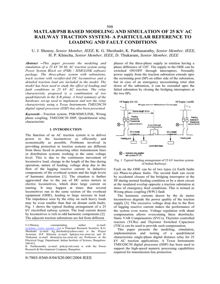
508 MATLAB/PSB BASED MODELING AND SIMULATION OF 25 KV AC RAILWAY TRACTION SYSTEM- A PARTICULAR REFERENCE TO LOADING AND FAULT CONDITIONS U. J. Shenoy, Senior Member, IEEE, K. G. Sheshadri, K. Parthasarathy, Senior Member, IEEE, H. P. Khincha, Senior Member, IEEE, D. Thukaram, Senior Member, IEEE Abstract --This paper presents the modeling and simulation of a 25 kV 50 Hz AC traction system using Power System Block set (PSB) / SIMULINK software package. The three-phase system with substations, track section with rectifier-fed DC locomotives and a detailed traction load are included in the model. The model has been used to study the effect of loading and fault conditions in 25 kV AC traction. The relay characteristic proposed is a combination of two quadrilaterals in the X-R plane. A brief summary of the hardware set-up used to implement and test the relay characteristic using a Texas Instruments TMS320C50 digital signal processor (DSP) has also been presented. phases of the three-phase supply in rotation having a phase difference of 120o. The supply to the OHE can be switched ON/OFF through interruptors. Normally power supply from the traction substation extends upto the sectioning post (SP) on either side of the substation, but in case of an emergency necessitating total shut down of the substation, it can be extended upto the failed substation by closing the bridging interruptors at the two SPs. Keywords—Traction system, PSB/SIMULINK, Wrong phase coupling, TMS320C50 DSP, Quadrilateral relay characteristic 1. INTRODUCTION The function of an AC traction system is to deliver power to the locomotives as efficiently and economically as possible. Problems involved in providing protection to traction systems are different from those faced in protecting other transmission lines or distribution systems working at the same voltage level. This is due to the continuous movement of locomotive load, change in the length of the line during operation, nature of loading, voltage drop due to the flow of the lagging reactive current in inductive components of the overhead system and the high levels of harmonic distortion [1]. The situation is further aggravated due to the use of DC series motors in electric locomotives, which draw large current on starting. It may happen at times that several locomotives run in the same section of the overhead equipment (OHE), leading to large increase in load. The impedance seen by the relay on such heavy loads may be even smaller than that on distant earth faults. Fig. 1 shows the typical feeding arrangement of a 25 kV electrified railway system. The load current drawn by locomotives is rich in odd harmonic components [2]. The adjacent traction substations are fed from different U.J.Shenoy, corresponding author (e-mail: ujs@ee.iisc.ernet.in) is Principal Research Scientist, K.G. Sheshadri (e-mail: kg_sheshadri@yahoo.com) is the Project Assistant, H.P. Khincha (e-mail: hpk@ee.iisc.ernet.in) and D. Thukaram (e-mail: dtram@ee.iisc.ernet.in) are Professors in the Electrical Engg. Department, Indian Institute of Science, Bangalore560 012. K. Parthasarathy (e-mail: prdc@vsnl.com) is with the Power Research & Development Company, Bangalore. 0-7803-8560-8/04/$20.00©2004 IEEE Fig. 1. Typical feeding arrangement of 25 kV traction system of Indian Railways Fault on the OHE can be of two types (i) Earth faults (ii) Phase-to-phase faults. The second fault can occur by accidental closure of the bridging interruptor at the SP during normal feeding condition or by a short circuit at the insulated overlap opposite a traction substation at times of emergency feed conditions. This is termed as Wrong phase coupling (WPC) fault. The harmonic currents drawn by the dc motor locomotives degrade the power quality of the traction supply [3]. The excessive voltage drop due to the flow of lagging reactive current makes the performance of the system even worse. Voltage regulation with shunt compensation allows overcoming these drawbacks. Static VAR Compensators (SVCs), Thyristor controlled reactors (TCRs) and Thyristor Switched Capacitors (TSCs) can be used to provide such compensation. This paper presents the modeling, simulation, implementation and testing of a quadrilateral characteristic single-phase digital distance relay for 25 kV AC traction applications. A Texas Instruments TMS320C50 digital processor (DSP) has been used to support the high-speed numeric processing capabilities required for transmission line protection. 509 2. RAILWAY TRACTION SYSTEM MODEL In order to investigate the performance of faults and loading conditions, the OHE of a typical 25 kV traction system of the Indian Railways has been considered. The Power System Block set (PSB) of MATLAB/SIMULINK is a modern design tool used to build the simulation models for electric power system as well as its interactions with other systems [4]-[6]. The basic function blocks of the individual subsystems are developed initially and are interconnected to form the full system model. Each system element is modeled based on its specifications [7]. 2.1 Three-phase AC supply system A three phase 220 kV, 50 Hz AC supply system with the 220 kV single circuit transmission line has been modeled as shown in Fig. 2. The power received from the supply authority grid network is transmitted to the railway’s own transmission lines by a series of transformer and line sectioning facilities. The substations have been modeled as subsystems. A bridging interruptor modeled as a switch connected between Substation 1 (Sub1) and Substation 2 (Sub2) facilitates the simulation of WPC faults. with a small fault resistance has been used. The timing of the fault is provided by a timer block that goes high at the fault instant, thus closing the switch and providing a path to the ground. Fig. 3. Model of Substation 1 with traction feeder and loads 2.3 Locomotive model The locomotives are assumed to be of the conventional thyristor type with a total locomotive rating of 2.5 MW (rated at 25 kV). They are modeled as two halfcontrolled thyristor-diode bridge rectifiers with each rectifier having parameters of ON state resistance Ron = 1mΩ, forward voltage = 0.8 V, snubber resistance = 100 Ω. The upper and lower half-bridge converters convert AC voltage to a controlled DC voltage. AC voltage from the 25 kV feeder is reduced to the required voltage of the power converters. Each thyristor-diode bridge is fed from a 25 kV/ 2 X 400 V three winding single phase transformer having 8% impedance and saturable characteristics. Fig. 4 shows the locomotive model. 3. SIMULATION RESULTS AND ANALYSIS Fig. 2. Model of three-phase supply grid with substations 2.2 Substation and Track section model Fig. 3 shows the modeling of Substation 1. The modeling of Substation 2 is identical to that of Substation 1. The 25 kV supply for traction system is drawn through a single phase step down transformer. This is modeled as a 25 MVA, 220 kV/25kV, two winding single phase transformer with impedance of 12% at 25 MVA base. The average length of the catenary to be protected during normal feed conditions is 40 km. This feeder is modeled as ten 4 km pi sections, each having a longitudinal impedance of 0.169+j0.432 Ω/km at 50 Hz and shunt capacitance of 0.011 μF/km [8]. This facilitates the simulation of earth faults from 10% to 90% of the line. The TSC is modeled appropriately by choosing reactor and capacitor values tuned to a particular frequency (i.e. the third harmonic) and can reduce the harmonic pollution. In order to simulate earth faults, an ideal switch block In order to investigate the effects of the faults and loading conditions in the traction system, a number of cases have been studied with and without TSC. The load distributions have been coded as a number, with each case representing the number of fully loaded locomotives at the related loading points in Fig. 3 both in Substation 1 and Substation 2. For example, a load pattern of 1110 for Substation 1 means that there are 3 locomotives connected to the track section, one at 12 km, the second locomotive at 24 km and the third locomotive at 32 km. 3.1 Simulation waveforms Figs. 5-8 show some representative simulation waveforms of the feeder voltage and feeder current without the TSC. In order to study the effect of earth faults and WPC faults separately, initially earth faults were simulated at different points on the traction feeder (from 10% to 90% of the line) with the bridging interruptor open and fault block connected. The SIMULINK/PSB also facilitates the timing of the fault 510 by varying the timer parameters, fault resistance and location of the fault. The bridging interruptor was then closed with the earth fault block removed and the WPC simulation studies were carried out. The waveforms monitored at both the leading and lagging end substations are as shown in Fig. 7 and Fig. 8. Fig. 5 Waveforms for Case with 1 loco in Sub1, No locos in Sub2, No fault, loading conditions 4. RELAY CHARACTERISTIC Quadrilateral relay characteristics provide higher resistive coverage than mho characteristics. Quadrilateral characteristics have proved very versatile in protecting railway overhead lines. They permit each relay to protect longer sections of the line, while avoiding the traction load [9]. Heavy traction loading can lead to load encroachment problems. In the proposed digital distance relay, the quadrilateral characteristic is as shown in Fig. 9. The detection of the fault using the above logic applies to Zone-1 protection. The relay reach settings and other parameters have been chosen as given in Table I. Usually protection for a WPC fault on traction OHE is provided by an offset mho relay and that on earth fault by a plain mho relay. But due to overlap of the two characteristics, some times the earth fault relay operates on WPC fault too. A tripping decision based only on angle is not sufficient enough to detect. The impedance seen by the relay on WPC fault at the substation with lagging voltage always lies in the second quadrant of the relay characteristic while that for earth fault lies in the first quadrant. Therefore, these two faults can be discriminated by having two relay characteristics as shown in Fig. 9. Fig. 6 Waveforms for Case with 2 locos in Sub1, 1 loco in Sub2, Earth fault at t=0.13 s at 80% of line. Fig. 9. Quadrilateral relay characteristic for traction feeder 5. DSP BASED HARDWARE SETUP FOR IMPLEMENTING RELAY CHARCATERISTIC Fig. 7. Waveform for Case with 3 locos in Sub1, No loco in Sub2 (Leading end), WPC fault at t=0.14 s Fig. 8 Waveforms for Case with 3 locos in Sub1, No loco in Sub2 (Lagging end), WPC fault at t=0.14 s Fig. 10 shows the hardware set-up for implementation of the proposed relay. The data files containing the samples of feeder voltage and current obtained from simulation studies of traction system are reproduced on a real-time basis using a 12-bit Burr Brown DAC-4815 Digital to Analog converter card interfaced to PC with a sampling frequency of 3 kHz after suitable signal conditioning. The relaying hardware has been built using Texas Instruments TMS320C50 DSP hardware platform. A 12-bit Burr Brown ADS-7804 Analog-toDigital Converter (ADC) with conversion time of 7.6μs has been interfaced to the DSP hardware to acquire incoming samples of feeder voltage and current. The relaying software including signal acquisition, processing of data and the relaying logics for 511 quadrilateral characteristic are written in the assembly language of the TMS320C50 DSP processor. The Fourier Full cycle algorithm with 12-sample window has been used to evaluate the magnitude of incoming signals and to calculate the impedance. The relay characteristic has been tested using the simulated cases of the traction system. The computations for processing of relaying algorithm including the relaying logic are carried out within 120μs. Table I. Typical Relay characteristic parameters Table II. Typical results of impedance 7. CONCLUSIONS 6. RESULTS AND DISCUSSION The performance of the relay has been evaluated using the data simulated from MATLAB/SIMULINK/PSB based studies. The earth fault studies have been carried out for various locations along the traction feeder for different timing of the faults. The performance of the relay for various harmonics in the feeder voltage and current has also been analysed using the Fourier program. For each such case the phase of the feeder voltage and current in both substations and also the impedance seen by the relay at both substation has been tabulated. The values of impedance for the simulated cases have been indicated in Table II. It is seen that earth fault is detected in first quadrant of relay characteristic. For WPC fault, the relay at the lagging end detects the fault as seen in the second quadrant of the relay characteristic. Fig. 10 Block diagram of the hardware set-up for relay characteristic implementation This paper describes modeling and simulation of a 25 kV AC traction railway system using MATLAB/PSB. The software supports the accurate modeling and simulation of the system, creation of earth and wrongphase coupling faults. The faults are accurately detected in the proposed relay characteristic, which has been implemented on the TMS320C50 DSP processor. The results show that the proposed simulation is accurate and can prove to be a tool to develop high-speed reliable distance relays for traction feeders. 8. REFERENCES [1] R. P. Maheshwari, H. K. Verma, “Adaptive Digital relay for comprehensive distance protection of traction overhead equipment”, Developments in Power system protection, Conference Publication No. 434, IEE, 25-27th March 1997, pp. 331-337. [2] Gao Shibin, He Weijun, Chen Xiaochuan, “Study on microprocessor based adaptive protection relay for heavy duty electric traction system”, Developments in Power System Protection, Sixth Intl. Conf., Pub. No. 434, IEE, 25th-27th March 1997, pp. 319-322. [3] G. Celli, F. Pilo, S.B. Tennakoon, “Voltage Regulation on 25 kV AC railway systems by using Thyristor switched capacitor”, Proceedings of 9th Intl. Conference on Harmonics and Quality of Power, Vol. 2, Oct. 2000, pp. 633-638. [4] “Power System Blockset User’s Guide”, The Mathworks Inc., Natick, MA, January 1999. [5] “Using Simulink”, the Mathworks Inc., Natick, MA, January 1999. [6] “Using MATLAB”, The Mathworks Inc., Natick, MA, January 1999. [7] “Static distance protection relay with parallelogram characteristic for 25 kV AC single phase, 50 Hz traction Overhead equipment”, Specification No. ETI/PSI/141 (10/90), Research Designs and Standards organization, Ministry of Railways, India. [8] Pee-Chin Tan, Robert E. Morrison, Donald Grahame Holmes, “Voltage form factor control and reactive power compensation in a 25 kV Electrified railway system using shunt active filter based on voltage detection”, IEEE Transactions on Industry Applications, Vol. 39, No. 2, March/April 2003, pp. 575-581. [9] M.J.Domzalski, K.P.Nickerson, P.R.Rosen, “Application of mho and quadrilateral distance characteristics in power systems”, Developments in Power System Protection, Seventh Intl. Conf., Pub. No. 479, 9-12 April 2001, pp. 555-558. [10] “The TMS320C5X User’s Guide”, Texas Instruments, USA, January 1993. [11] “The Burr-Brown IC Data book-Data Conversion Products”, Burr Brown Corporation, USA, 1995.
