Technical Data
DALI Digital to Analog Converter
Catalog#
Prepared by
Project
Date
Comments
Type
Overview
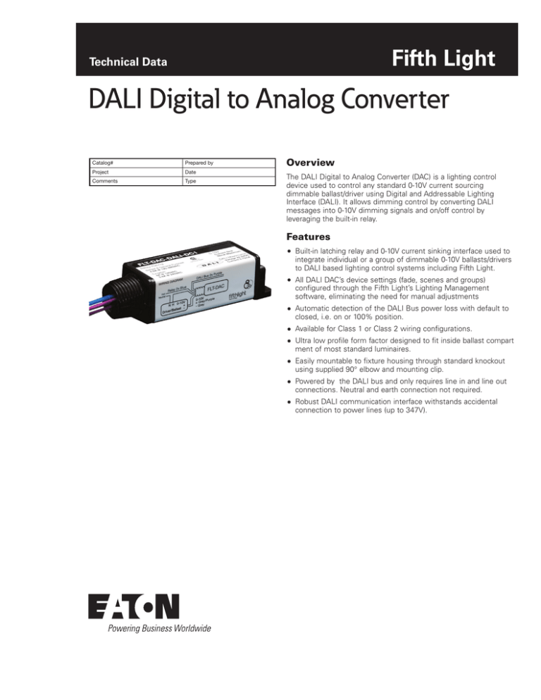
The DALI Digital to Analog Converter (DAC) is a lighting control
device used to control any standard 0-10V current sourcing
dimmable ballast/driver using Digital and Addressable Lighting
Interface (DALI). It allows dimming control by converting DALI
messages into 0-10V dimming signals and on/off control by
leveraging the built-in relay.
Features
Built-in latching relay and 0-10V current sinking interface used to
integrate individual or a group of dimmable 0-10V ballasts/drivers
to DALI based lighting control systems including Fifth Light.
All DALI DAC’s device settings (fade, scenes and groups)
configured through the Fifth Light’s Lighting Management
software, eliminating the need for manual adjustments
Automatic detection of the DALI Bus power loss with default to
closed, i.e. on or 100% position.
Available for Class 1 or Class 2 wiring configurations.
Ultra low profile form factor designed to fit inside ballast compart
ment of most standard luminaires.
Easily mountable to fixture housing through standard knockout
using supplied 90° elbow and mounting clip.
Powered by the DALI bus and only requires line in and line out
connections. Neutral and earth connection not required.
Robust DALI communication interface withstands accidental
connection to power lines (up to 347V).
DALI Digital to Analog Converter
June 2015
Specifications
Dimensions
(Inches/mm)
Catalog #
LCP
Enclosure
Dimensions: 1”H x 3.94”W x 1.125”D
(25.4mm x 100mm x 28.6mm)
Temperature: 32°F to 104°F (0°C to 40°C)
Relative Humidity: 10% to 90% (non-condensing)
For indoor use only
Environment
Relay Output
Specifications
SIde VIEW
Input Voltage: 120-480 VAC +/-10%
1.0 /
25.4
Maximum Ballast/General Load: 4.5A @ 120-480 VAC
Maximum Tungsten Load: 8A @ 120 VAC,
5.8A @ 240 VAC
3.94 /
100.0
Input Frequency: 50/60 Hz
Control
Specification
Communication Interface: Digital Addressable Lighting
Interface (DALI) and Analog Dimming
DALI Current Draw: 3.75mA
Analog Dimming Current Draw: 0-10 VDC, 50mA max
current sink only
Angled view
Note: Upon first power up allow 4-6 seconds before
sending DALI command
Wiring
Mounting
Standards
1.125 /
28.58
Relay: 18 AWG solid TFN non-polarized pair
0-10V Dimming: 18 AWG solid TFN polarized pair
DALI Communication: 18 AWG stranded PTFE plenum
rated non-polarized pair
In fixture or junction box mounting only. Refer to
Wiring Diagram section of Spec Sheet for proper
wiring details
UL 916 Listed
UL 924 Listed
Meets NEC, OSHA and NFPA Safety Codes
C
1.0 /
25.4
3.94 /
100.0
US
Emergency Lighting
Accessory - UL 924
Open Energy Management Eq.
2CFO
Wiring Diagram
FLT-DAC-DALI-DC1
DALI Bus 2x Purple
Hot
Neutral
Relay 2x Blue
FLT-DAC
N H 0-10V
+
Driver/Ballast -
0-10V
+ Grey/Purple
- Grey
FLT-DAC-DALI-DC2
Hot
Neutral
Relay 2x Blue
N H 0-10V
+
Driver/Ballast -
FLT-DAC
DALI Bus 2x Purple
0-10V
+ Grey/Purple
- Grey
NNote: Install in accordance with all applicable National and local electrical &
building codes.
NNote: Specifications subject to change without notice.
2
www.eaton.com/lightingsystems
DALI Digital to Analog Converter
June 2015
Sample System Topology
DALI COMMUNICATION BUS
Maximum of up to 64 devices on each DALI Bus.
All devices must be within 900 feet of the
Lighting Control Panel (LCP).
16/2 AWG recommended wire.
Scene 1
Scene 2
Scene 3
Scene 4
DALI FIELD
RELAY
DALI DIMMABLE
BALLAST
11:46 06/26/09
DALI MULTI
SENSOR
DALI DAC
0-10 VDC
10%
10%
20%
3
30%
4
40%
DALI
Wallstation
1000
FIFTH LIGHT TECHNOLOGY
1
2
DALI DIMMING
MODULE
DALI RELAY PANEL
Units Are: 1027.1028
LIGHTS
LIGHTING
CONTROL PANEL
GROUPS
SCENES
SUPPORT
VOIP PHONE
TOUCH
SCREEN
MOBILE
APP
ETHERNET
NETWORK SWITCH
CENTRAL SERVER UNIT
Ordering
Catalog #
LCP
FLT-DAC-DALI-DC1
Digital to Analog Converter - DALI wiring
exits with line voltage wiring for Class 1
installations of the DALI bus.
Digital to Analog Converter - DALI wiring
exits separate from line voltage wiring for
Class 2 installations of the DALI bus.
FLT-DAC-DALI-DC2
Eaton
1000 Eaton Boulevard
Cleveland, OH 44122
United States
Eaton.com
Eaton
Lighting systems - Controls products
203 Cooper Circle
Peachtree City, GA 30269
www.eaton.com/lightingsystems
© 2015 Eaton
All Rights Reserved
Printed in USA
Publication No. TD503019EN
June 30, 2015
Eaton is a registered trademark.
All other trademarks are property
of their respective owners.


