INSTALLATION INSTRUCTIONS V90184 REV A Avoid Fire or Electric Shock
advertisement

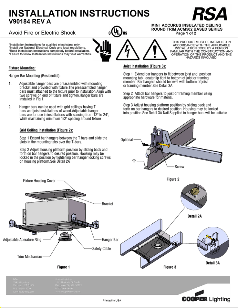
INSTALLATION INSTRUCTIONS V90184 REV A MINI ACCURUS INSULATED CEILING ROUND TRIM ACM502 BASED SERIES Page 1 of 2 Avoid Fire or Electric Shock THIS PRODUCT MUST BE INSTALLED IN ACCORDANCE WITH THE APPLICABLE INSTALLATION CODE BY A PERSON FAMILIAR WITH THE CONSTRUCTION AND OPERATION OF THE PRODUCT AND THE HAZARDS INVOLVED. *Installation Instructions for qualified electricians only. *Install per National Electrical Code and local regulations. *Read Installation Instructions completely before installation. *Failure to follow Installation Instructions may void warranties. Fixture Mounting: Joist Installation (Figure 3): Hanger Bar Mounting (Residential): Step 1 Extend bar hangers to fit between joist and position mounting tab locater lip tight to bottom of joist or framing member. Bar hangers should be level with bottom of joist or framing member.See Detail 3A. 1. 2. Adjustable hanger bars are preassembled with mounting bracket and provided with fixture.The preassembled hanger bars must attached to the fixture prior to installation.Align with two screws on end of fixture and tighten.Hanger bars are installed in Fig.1. Hanger bars can be used with grid ceilings having T bars and joist installations of wood.Adjustable hanger bars are for use in installations with spacing from 12" to 24", while maintaining minimum 1/2" spacing around fixture Step 2 Attach bar hangers to joist or framing member using appropriate hardware for material. Step 3 Adjust housing platform position by sliding back and forth on bar hangers to desired position. Housing may be locked into position See Detail 3A.Nail Supplied in hanger bars will be suitable. Grid Ceiling Installation (Figure 2): Step 1 Extend bar hangers between the T bars and slide the slots in the mounting tabs over the T-bars. Step 2 Adjust housing platform position by sliding back and forth on bar hangers to desired position. Housing may be locked in the position by tightening bar hanger locking screws on housing platform.See Detail 2A Optional "T" Screw Figure 2 Fixture Housing Cover Bracket Detail 2A Adjustable Aperature Ring Hanger Bar Safety Cable Trim Mechanism Figure 1 Figure 3 Detail 3A INSTALLATION INSTRUCTIONS V90164 REV A MINI ACCURUS INSULATED CEILING ROUND TRIM ACM502 BASED SERIES Page 2 of 2 Avoid Fire or Electric Shock THIS PRODUCT MUST BE INSTALLED IN ACCORDANCE WITH THE APPLICABLE INSTALLATION CODE BY A PERSON FAMILIAR WITH THE CONSTRUCTION AND OPERATION OF THE PRODUCT AND THE HAZARDS INVOLVED. *Installation Instructions for qualified electricians only. *Install per National Electrical Code and local regulations. *Read Installation Instructions completely before installation. *Failure to follow Installation Instructions may void warranties. Adjustable Aperture Ring Rotational Adjustment Ring Lock Knob 10. Fixture Ceiling Chaulk Adjustable Aperture Ring Ball Catch Trim Mechanism Figure 4 3. Install Ceiling drywall up to Adjustable Aperature Ring on Fixture See Fig. 4. 4. Position Adjustable Aperature Ring to be in plane with Ceiling by sliding up or down.See Fig.4 5. Connect Safety Cable attached to Trim to Fixture by inserting Safety Cable through opening in Fixture and inserting Snap Hook (See Fig. 1) on end of Safety Cable into hole in Bracket attached to inside of fixture.Install trim mechanism into fixture by pressing firmly to retain Ball Detent Catches. See Fig.4. IF LOCKING KNOB IS LOCKED: 11. Remove Trim Mechanism from Fixture. 12. Loosen Lock Knob inside Fixture. 13. To lock positioning, remove Trim Mechanism being careful not to change position. 14. Tighten Lock Knob inside Fixture to lock Rotational adjustment Ring. See Fig.5. 15. Be careful to align Tab Alignment Feature on Trim Mechanism with Tab Alignment feature Notch in Rotational Adjustment Ring. 16. Connect Safety Cable attached to Trim to Fixture by inserting Safety Cable through opening in Fixture and inserting Snap Hook (See Fig. 1) on end of Safety Cable into hole in Bracket attached to inside of fixture.Install trim mechanism into fixture by pressing firmly to retain Ball Detent Catches.See Fig.4. Rotational Adjustment Ring Tab Alignment Feature Notch Apply caulking or mudding compound around perimeter edge of Adjustable Aperature Ring and drywall cutout. 360 Rotational Lamp Adjustment IF LOCKING KNOB IS UNLOCKED: 6. Rotate Trim Mechanism to desired lamp bean position by turning Trim Mechanism up to 360 Degrees. 7. To lock positioning, remove Trim Mechanism being careful not to change position. 8. Tighten Lock Knob inside Fixture to lock Rotational adjustment Ring. See Fig.6. 9. Be careful to align Tab Alignment Feature on Trim Mechanism with Tab Alignment feature Notch in Rotational Adjustment Ring while installing trim after rotational adjustment. Ceiling Joist Locking Knob Fixture Figure 5 (Fixture Cover Removed for Clarity)


