6.002 Demo# 17A ( Load Set up demo#17A )
advertisement
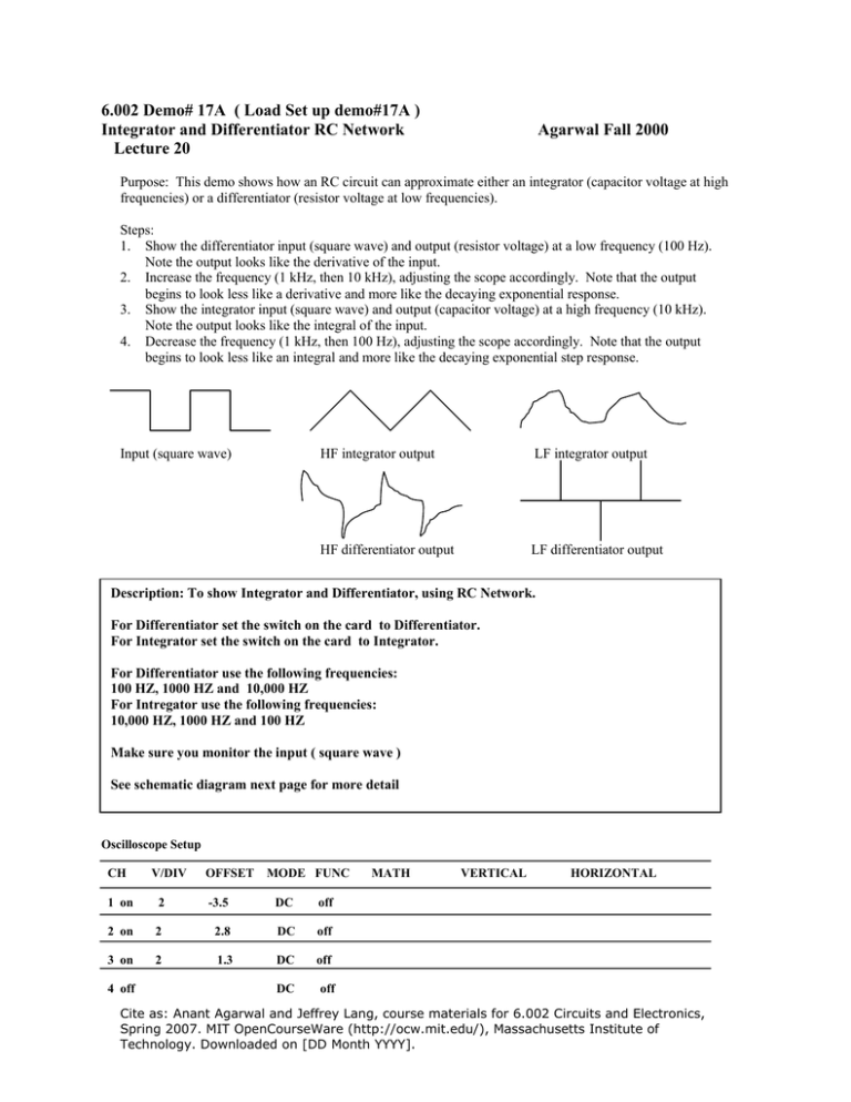
6.002 Demo# 17A ( Load Set up demo#17A ) Integrator and Differentiator RC Network Lecture 20 Agarwal Fall 2000 Purpose: This demo shows how an RC circuit can approximate either an integrator (capacitor voltage at high frequencies) or a differentiator (resistor voltage at low frequencies). Steps: 1. Show the differentiator input (square wave) and output (resistor voltage) at a low frequency (100 Hz). Note the output looks like the derivative of the input. 2. Increase the frequency (1 kHz, then 10 kHz), adjusting the scope accordingly. Note that the output begins to look less like a derivative and more like the decaying exponential response. 3. Show the integrator input (square wave) and output (capacitor voltage) at a high frequency (10 kHz). Note the output looks like the integral of the input. 4. Decrease the frequency (1 kHz, then 100 Hz), adjusting the scope accordingly. Note that the output begins to look less like an integral and more like the decaying exponential step response. Input (square wave) HF integrator output LF integrator output HF differentiator output LF differentiator output Description: To show Integrator and Differentiator, using RC Network. For Differentiator set the switch on the card to Differentiator. For Integrator set the switch on the card to Integrator. For Differentiator use the following frequencies: 100 HZ, 1000 HZ and 10,000 HZ For Intregator use the following frequencies: 10,000 HZ, 1000 HZ and 100 HZ Make sure you monitor the input ( square wave ) See schematic diagram next page for more detail Oscilloscope Setup CH V/DIV OFFSET MODE FUNC 1 on 2 -3.5 DC off 2 on 2 2.8 DC off 3 on 2 1.3 DC off 4 off DC MATH VERTICAL HORIZONTAL off Cite as: Anant Agarwal and Jeffrey Lang, course materials for 6.002 Circuits and Electronics, Spring 2007. MIT OpenCourseWare (http://ocw.mit.edu/), Massachusetts Institute of Technology. Downloaded on [DD Month YYYY]. Horizontal: 5 ms Acquisition: AUTO AUTO Waveform Generator Setup UNIT WAVE AMP 4 Trigger: Power Supply Setup OFFSET FREQ +6 +25 off FG1 Square 1* 0 CH1 100 & 1000 & 10,000 HZ ! off -25 OUTPUT off Trigger: INT • Amplitude depends on the Prof.! ! See above for integrator frequencies set up Cite as: Anant Agarwal and Jeffrey Lang, course materials for 6.002 Circuits and Electronics, Spring 2007. MIT OpenCourseWare (http://ocw.mit.edu/), Massachusetts Institute of Technology. Downloaded on [DD Month YYYY].
