Greengate
Technical Data
CEPC – Emergency Power Control
Catalog#
Prepared by
Project
Date
Comments
Type
Overview
The Emergency Power Control (CEPC) device allows the control
of emergency lighting by any Greengate lighting control panel or
occupancy sensor.
Features
Eliminates energy waste by allowing emergency lighting to be
switched
Fail safe operation
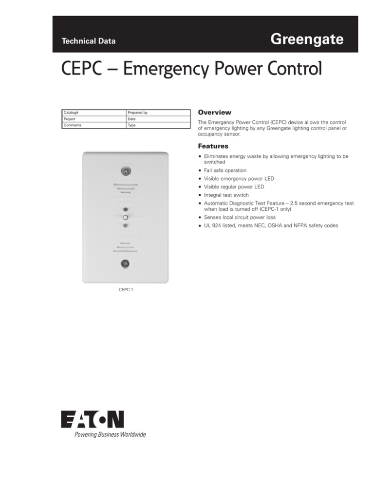
Visible emergency power LED
Visible regular power LED
Integral test switch
Automatic Diagnostic Test Feature – 2.5 second emergency test
when load is turned off (CEPC-1 only)
Senses local circuit power loss
UL 924 listed, meets NEC, OSHA and NFPA safety codes
CEPC-1
CEPC – Emergency Power Control
April 2015
Specifications
Connections
Load Ratings
Size
Mounting
Color
Operating
Environment
Compatibility
Standards
2
Normal Power Sensing: 120V or 277V
Emergency Power: 120V or 277V
Normal Power Switching: 120V or 277V
20A Ballast Load Rating
1800W Incandescent Load Rating at 120V
1500W Incandescent Load Rating at 277V
(CEPC-1 only)
Body Size: 2.875”H x 1.75”W x 1.75”D
Flushmount Size: 4.75”H x 2.75”W x 0.25”D
Mounts to a 4.688” junction box with single gang
plater ring
UL 94-5VA Rated Plastic
White
Temperature: 32°F - 140°F (0°C - 60°C)
For indoor use only
CEPC-1: Greengate LiteKeeper, ControlKeeper
Relay Panels and Occupancy Sensor
CEPC-1-D: Greengate ControlKeeper 4A or Room
Controller
UL Approved
UL 924 Listed
www.coopercontrol.com
Description/Operation
The CEPC senses a local, single normal power circuit. As long as
normal power is present, the CEPC permits normal and emergency
switching of the lighting load from Greengate lighting control panels
or occupancy sensors. If normal power is lost for any reason, the
CEPC will force the connected emergency fixtures ON. The CEPC
can be wired as either a control device along with a relay panel
and occupancy sensor, or as a shunt to bypass line voltage devices
when normal power fails. The CEPC-1-D is a universally compatible
device that allows control of 4-wire emergency dimming loads.
When normal power is lost, the CEPC-1-D will force the emergency
fixtures to the full bright condition. Both CEPC models include a
test switch feature for verifying proper functionality. In addition, the
CEPC-1 model also provides an automatic test feature. Under normal
operation, when the controlled load is turned OFF, the emergency
lighting will remain ON an additional 2.5 seconds, providing safety
and convenience while leaving the area and eliminating the need of
special equipment to test the emergency control of the device.
Installation
The CEPC can be installed down line of a Greengate lighting control
panel or occupancy sensor and switchpack. The CEPC should be
located next to the emergency fixture it is controlling.
CEPC – Emergency Power Control
April 2015
Wiring Diagrams
Wiring Diagram for 2-Wire
Non-Dimming
Loads (w/ Relay Panel)
Wiring Diagram for 2-Wire Non Dimmed Loads
2-Wire Non-Dimmed
CEPC
Emergency
Power
Blue
Blue/
White
20A
Test
Emergency
Panel
Yellow
Emergency
Lighting Load
Blue/
White
Test
White
Red
Black/
Orange
Utility
Power
Regular Neutral
Regular Line Hot
CEPC Wire #
Description
Blue
Emergency Hot
iLumin Connection
Yellow
Emergency Switchleg
Blue/White
Emergency Neutral
Black/Orange
Regular Hot (Sensing)
Transformer Power
Red
Switchleg
Relay Load Terminal Block
White
Regular Neutral
Transformer Neutral Wire
Greengate
Relay Card Connection
Switchleg
Load
20A
Line
Normal Panel
2 - Wire Non Dimmed
CEPC
Wire #
Diagram
iLumin Connection
Wiring
for Description
2-Wire
Non-Dimming
Loads
Switchpack)
for(w/
2-Wire
Blue Wiring Diagram
Emergency
Hot Non Dimmed Loads
Yellow
Emergency Switchleg
Blue
Black/Orange
Blue/
Emergency
Regular Power
Hot (Sensing)
Red White
Emergency White
Panel
Switchleg
Test
Test
Yellow
Emergency
Transformer Power
Lighting Load
Blue/
Relay Load Terminal Block
White
Regular Neutral
Blue
Blue/White
Blue
Yellow
Greengate
Switchpack Connection
Switchleg - Blue
Neutral
Hot - Blue
*Hot
20A
Greengate Switchpack
Connection
Description
Emergency
Hot
2 - Wired
Non Dimmed
CEPCYellow
Wire #
White
Red
CEPC Wire #
Transformer Neutral wire
Utility
Power
Black/
Orange
20A
2-Wire Non-Dimmed
CEPC
Emergency Neutral
Blue/White
Emergency Switchleg
Description
Greengate Switchpack Connection
Emergency Neutral
Emergency Hot
Black/Orange
Regular Hot (Sensing)
Emergency Switchleg
Red
Blue/White
Switchpack Load Terminal
Block
Switchleg
Emergency Neutral
Black/Orange
White Regular Hot (Sensing)
Regular
Regular Hot
Regular Hot
Neutral
Regular Neutral
Red
Switchleg
Switchpack Load Terminal Block
White
Regular Neutral
Regular Neutral
*Use Black lead for 120 VAC,
Use Orange lead for 277 VAC
Normal Panel
Wiring Diagram for 4-Wire
Dimming Loads
4-Wire Dimming
CEPC-1-D
7 EM
Neutral
5 EM Hot
Emergency
Power
Test
Emergency
Panel
6 EM Load
RED
Test
Emergency
Lighting Load
(Violet 0-10V)
Utility
Power
Blue
3
(Violet 0-10V)
1 or 2
4
20A
Regular Neutral
Regular Line Hot (Sensing Circuit)
Load
Line
VIOGRY
1 1
CK4A or Room Controller
0-10V outputs
CK4A or Room Controller
Relay
0-10V
Gray wire
CEPC-1-D
Wire #
Color
Description
Greengate
Connection
1
Black
Regular Hot (120V)
Constant Hot and
Relay Line
2
Orange
Regular Hot (277V)
Constant Hot and
Relay Line
3
Red
Switched Hot
Relay Load
4
White
Regular Neutral
5
Blue
Emergency Hot
6
Yellow
Emergency Load Hot
7
White/Blue
Emergency Neutral
Blue
Dimmer Violet (0-10V +)
Red
To Load Violet (0-10V +)
Black
Cap Off
Panel Dimmer
Output Violet
www.coopercontrol.com
3
CEPC – Emergency Power Control
April 2015
Ordering
This is an accessory for Greengate Lighting Control Panels and
Greengate Occupancy Sensors. When ordering, specify the CEPC as
a separate accessory.
Model
Description
Rating
CEPC-1
CEPC-1-D
CEPC-1-UM
CEPC-1-CUL
CEPC-1-D-CUL
Emergency Power Control
0-10V Load Emergency Power Control 120V
Emergency Power Control (Made in USA)
Emergency Power Control for Canada
0-10V Load Emergency Power Control for Canada
120V
120V
120V
120V
120V
or
or
or
or
or
277V
277V
277V
277V
277V
Eaton
1000 Eaton Boulevard
Cleveland, OH 44122
United States
Eaton.com
Eaton
Lighting Systems – Controls Products
203 Cooper Circle
Peachtree City, GA 30269
coopercontrol.com
© 2015 Eaton
All Rights Reserved
Printed in USA
Publication No. TD503005EN
April 23, 2015
Eaton is a registered trademark.
All other trademarks are property
of their respective owners.


