Technical Data
Effective January 19, 2015
PD216 – Power Dimmer
Catalog#
Prepared by
Project
Date
Comments
Type
Overview
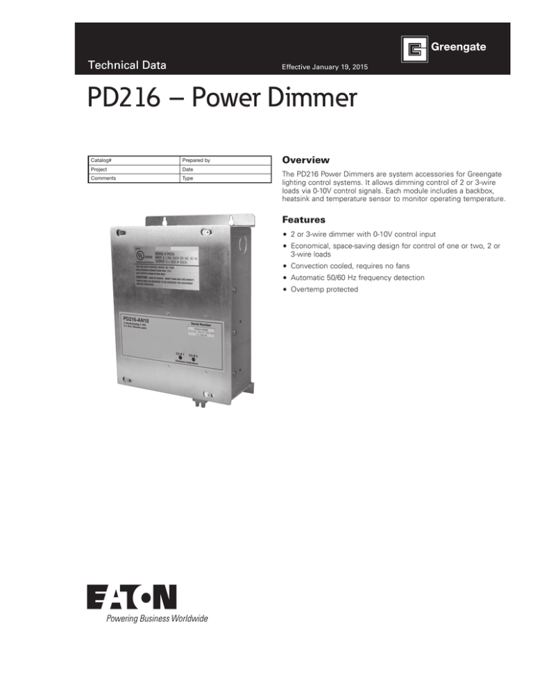
The PD216 Power Dimmers are system accessories for Greengate
lighting control systems. It allows dimming control of 2 or 3-wire
loads via 0-10V control signals. Each module includes a backbox,
heatsink and temperature sensor to monitor operating temperature.
Features
2 or 3-wire dimmer with 0-10V control input
Economical, space-saving design for control of one or two, 2 or
3-wire loads
Convection cooled, requires no fans
Automatic 50/60 Hz frequency detection
Overtemp protected
Technical Data
PD216 – Power Dimmer
January 2015
Specifications
Size & Weight
Wiring Diagrams
11.75”H X 8.3”W X 4.12”D
Approximately 5 pounds
120V or 277V, 50/60 Hz
120V or 277V, 50/60 Hz
2 X 1920W @ 120 VAC, 2 x 4500W @ 277 VAC
Max Connected Load 16A
For indoor use only
Electrical Data
Output
Operating
Environment
PD216-AN10-120
PD216-AN10-277
2 Circuit 20A Power Dimmer
2 Cir
Breaker
Breakers should be
on the same phase.
Line
H1
Dimmer
Output 1
Load 1
upto 1920W
Neutral
Neutral
Bus
To Breaker Panel
Neutral Bus
upto 1920W
Dimmer
Output 2
Description/Operation
Load 2
H2
Breakers should be
on the same phase.
Line
Breaker
The PD216 Power Dimmers dim 2 or 3-wire loads in response to a
0-10V control signal. This enables Greengate 0-10V dimming panels
to control 2 or 3-wire load types directly without the need for
architectural dimming panels. The PD216 control input wires directly
to the panel 0-10V dimming outputs that would typically drive
dimming ballasts.
The Load should be
run through relay in the
lighting control panel to
turn OFF.
PD216-AN10-120
Installation
PD216-AN10-3W-120
PD216-AN10-3W-277
2 Circuit 20A 3wire control Power Dimmer
PD216-AN10-277
system
accessory
will require mounting and wiring at the site.
2This
Circuit
20A Power
Dimmer
Breaker
H1
Dimmer
Output 1
Breaker
Breakers should be
on the same phase.
Line
H1
Dimmer
Output 1
Load 1
upto 1920W
Neutral
Neutral
Bus
Load 1
upto 1920W
Dimmer
Output 2
Breakers should be
on the same phase.
Line
Orange (Dimmed Hot)
Black (Switched Hot)
White (Neutral)
Load 2
LED1
LED2
NETWORK ALL OFF
50-022510-02
54-022510-
ADDRESS
LED3
ALL ON
1
2 3
4
5 6
7
8
Reset
J1
RS-232
Load 2
H2
To Breaker Panel
Neutral Bus
upto 1920W
upto 1920W
Dimmer
Output 2
Orange (Dimmed Hot)
Black (Switched Hot)
White (Neutral)
Neutral
Neutral
Bus
To Breaker Panel
Neutral Bus
Breakers should be
on the same phase.
Line
SW1
SW1 SW2 SW3
Breakers should be
on the same phase.
H1
H2
Line
J2
Breaker
+NET-NET
The Load should be
run through relay in the
lighting control panel to
turn OFF.
U5
PCI-NET
The Load should be
run through relay in the
lighting control panel to
turn OFF.
CAN-RX
CAN-TX
LED4
LED5
U2
J3
PCI-NET
Breaker
U1
U6
L1 L2 L3 L4
J4
J5
U7
TB1
C20
PS1
U8
LED6
RSC STAT
U9
J6
SR1
L1
PCI-NET TERM
S1
RESET PICS
U11
U10
SC1
C29
REG1
REG2
REG3
LED7
U12
SWIN STAT
U16
U15
U13
U16
U15
U14
U13
U17
U14
U17
U18
C40
C47
U19
U19
ANALOG INPUTS
AN AN AN AN
1 2 3 4
TB3
TB4
DIMMING OUTPUTS
TB5
SWITCH IN
VIO GRY VIO GRY VIO GRY IN
2 2
ANALOG COM
Violet terminal
to violet pigtail
of IDM
3 3
4 4
IN LS IN
IN LS
1 +24 2 1 3 +24 4 2 TP1
Gray terminal to
gray pigtail of of
IDM
TB3
AN AN AN AN
1 2 3 4
ANALOG COM
DIMMING OUTPUTS
TB4
TB5
U20
SWITCH INPUTS
TB6
VIO GRY VIO GRY VIO GRY VIO GRY IN
1
1
2 2
3 3
4 4
IN LS IN
IN LS IN
IN LS IN
IN LS
1 +24 2 1 3 +24 4 2 TP1 5 +24 6 3 7 +24 8 4
2 Circuit 20A
8
PCI-NET
SW3
LOAD
C20
K3
U9
J6
SR1
L1
PCI-NET TERM
Q4
REG2
REG3
SWIN STAT
SR2
POWER
U16
U15
U16
U15
U14
U13
U17
C48
U14
U17
L2
U18
C40
C47
U19
BR1
U19
ANALOG INPUTS
TB3
TB4
DIMMING OUTPUTS
TB5
SWITCH IN
TB3
DIMMING OUTPUTS
TB4
TB5
U20
SWITCH INPUTS
TB6
TB2
LSO TEST
C49
J7 J8
LOCAL
AN AN AN AN
1 2 3 4
2
ANALOG COM
VIO GRY VIO GRY VIO GRY IN
2 2
3 3
4 4
IN LS IN
IN LS
1 +24 2 1 3 +24 4 2 TP1
Violet terminal
Gray terminal to
to violet pigtail
gray pigtail of of
of IDM
IDM
www.coopercontrol.com
AN AN AN AN
1 2 3 4
ANALOG COM
VIO GRY VIO GRY VIO GRY VIO GRY IN
1
1
2 2
3 3
4 4
LOAD
LED7
U12
C39
IN LS IN
IN LS IN
IN LS IN
IN LS
1 +24 2 1 3 +24 4 2 TP1 5 +24 6 3 7 +24 8 4 +24 GND
REMOTE
TB7
K4
U3
C29
REG1
LED7
LED9
U4
STATUS
RESET PICS
SC1
SW4
S1
U11
U10
TB4
LED6
MOV4
U8
LED5
PS1
RSC STAT
U13
LOAD
MOV3
Q3
TB1
U2
+NET-NET
J5
Violet 1
Violet 2
GND to Gray
N
Channel 1
L1 L2 L3 L4
U7
Di
O
LINE
U6
J4
TB2
Q2
LED3
U1
PCI-NET
U5
+
TB3
LED5
U2
J3
SW2
U1
50-022110-01
J2
Match violet terminal wire from the
CK4A dimming channel to the +
terminal on the PD216.
LINE
LED4
C
CAN-TX
LINE
RS-232
SW1 SW2 SW3
H1
CAN-RX
MOV1
Reset
K1
7
MOV2
5 6
K2
4
Q1
2 3
SW1
1
SW1
TB1
50-022510-02
54-022510-
ADDRESS
LED3
ALL ON
J1
LED1
LED2
PCI 2005 X4 SRC
LED1
NETWORK ALL OFF
-
+
Channel 2
-
Match gray terminal wire from CK4A dimming
channels to the - terminal on the PD216.
Di
O
Technical Data
PD216 – Power Dimmer
January 2015
Wiring Diagrams
50-022510-02
54-022510-
ADDRESS
8
LED5
U5
TB1
LINE
LED3
U1
PCI-NET
SW2
U2
J3
Q2
50-022110-01
U1
U6
LOAD
CAN-TX
LED4
C
CAN-RX
TB2
RS-232
SW1 SW2 SW3
H1
J2
PCI-NET
TB3
Reset
MOV1
7
MOV2
5 6
K1
4
K2
2 3
Q1
1
SW1
SW1
LED3
ALL ON
J1
LED1
LED2
PCI 2005 X4 SRC
LED1
NETWORK ALL OFF
SW3
LOAD
C20
U2
PS1
LED6
SR1
L1
TB4
K3
PCI-NET TERM
LINE
RSC STAT
MOV4
U8
U9
J6
LED5
+NET-NET
J5
U7
LINE
Q3
MOV3
L1 L2 L3 L4
J4
TB1
Q4
REG1
REG2
LOAD
LED7
U12
SWIN STAT
SR2
POWER
U16
U15
U13
K4
U4
REG3
U3
C29
LED7
LED9
STATUS
RESET PICS
SC1
SW4
S1
U11
U10
U16
U15
U14
U13
U17
C48
U14
U17
L2
U18
C40
C47
U19
BR1
U19
ANALOG INPUTS
TB3
TB4
DIMMING OUTPUTS
TB5
SWITCH IN
TB3
DIMMING OUTPUTS
TB4
TB5
U20
SWITCH INPUTS
TB6
TB2
LSO TEST
TB7
C49
J7 J8
LOCAL
AN AN AN AN
1 2 3 4
VIO GRY VIO GRY VIO GRY IN
2 2
ANALOG COM
Violet terminal
to violet pigtail
of IDM
3 3
4 4
IN LS IN
IN LS
1 +24 2 1 3 +24 4 2 TP1
Gray terminal to
gray pigtail of of
IDM
AN AN AN AN
1 2 3 4
ANALOG COM
VIO GRY VIO GRY VIO GRY VIO GRY IN
1
1
2 2
3 3
4 4
C39
IN LS IN
IN LS IN
IN LS IN
IN LS
1 +24 2 1 3 +24 4 2 TP1 5 +24 6 3 7 +24 8 4 +24 GND
REMOTE
2 Circuit 20A Power Dimmer
Breaker
Match violet terminal wire from the
CK4A dimming channel to the +
terminal on the PD216.
+
H1
Dimmer
Output 1
Violet 1
Violet 2
GND to Gray
Neutral
Bus
Channel 1
-
+
Channel 2
-
Match gray terminal wire from CK4A dimming
channels to the - terminal on the PD216.
Breakers should be
on the same phase.
Line
Load 1
upto 1920W
Neutral
To Breaker Panel
Neutral Bus
upto 1920W
Dimmer
Output 2
H2
Load 2
Breakers should be
on the same phase.
Line
Breaker
The Load should be
run through relay in the
lighting control panel to
turn OFF.
www.coopercontrol.com
3
Technical Data
PD216 – Power Dimmer
January 2015
Ordering
This is an accessory for Greengate Lighting Control Systems. It is
not an integral part of the system. There is no factory assembly
needed.
Cat #
Description
PD216-AN10-120
PD216-AN10-3WB-120
PD216-AN10-277
PD216-AN10-3WB-277
2
2
2
2
Circuit
Circuit
Circuit
Circuit
20A
20A
20A
20A
120V
120V
277V
277V
Power Dimmer
3-wire control Power Dimmer
Power dimmer
3-wire control Power Dimmer
Eaton
1000 Eaton Boulevard
Cleveland, OH 44122
United States
Eaton.com
Eaton’s Cooper Controls Business
203 Cooper Circle
Peachtree City, GA 30269
coopercontrol.com
© 2014 Eaton
All Rights Reserved
Printed in USA
Publication No. ACC141054
January 19, 2015
Eaton is a registered trademark.
All other trademarks are property
of their respective owners.


