iLumin
Technical Data
LRM – Lighting Relay Module
Catalog#
Prepared by
Project
Date
Comments
Type
Overview
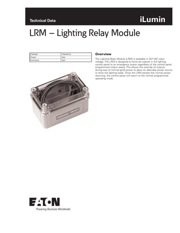
The Lighting Relay Module (LRM) is available in 347 VAC input
voltage. The LRM is designed to force all outputs in the lighting
control panel to an emergency scene regardless of the control panel
programmed output status. This allows the override of outputs
during loss of normal (grid) power to allow an alternate power source
to drive the lighting loads. Once the LRM senses the normal power
returning, the control panel will return to the normal programmed
operating mode.
LRM – Lighting Relay Module
July 2015
Specifications
General
Electrical Data
Mechanical Data
Compatibility
Standards
UL 924 Listed Accessory
Connects to normal power for monitoring
Architectural Dimming System must be fed
from alternate power
SC-UN, SC-FT, SC-RP, SC-RPB
Operation
The Lighting Relay Module provides a dry contact closure to the
Source Controller panel when normal (grid) power is lost. This
contact closure performs an override of all outputs in the enclosure
to an emergency scene. This override condition takes priority over
any output commands from the system controller and will remain in
effect until the contact closure from the LRM is removed.
Installation
The Lighting Relay Module can be installed next to the Source
Controller.
Wiring Diagram
L
Switch
Input 2
L
Switch
Input 1
L
DMX- DMX+ OV Shield
L
Ethernet link
DMX
Contact
closure
RS485- RS485+ OV Shield
+12V CAN-H DRAIN CAN-L DV
(red) (white) (gray) (blue) (black)
For Emergency panel configurations, ensure
the Source Controller is fed from an emergency
power source.
The LRM needs to provide a dry contact
maintained closure to the Switch Input 1 or
Switch Input 2 terminal on the Source Controller
input card.
Emergency actions can be programmed from
the Source Controller on board user interface.
RS485
iCAN
Switch
Input 1
Switch
Input 2
iLumin Contact inputs
To override On:
Connect dry contact from LRM to Switch Input 1 or
Switch Input 2.
Yellow (18 AWG)
NC
SPDT Relay
NO
When contact closes all relays/dimmers are forced
to an emergency scene. Contacts of the LRM will close
when normal power is lost.
Violet
C (18 AWG)
To Normal Power Circuit
347 VAC = Brown
(16 AWG)
Neutral = White
(16 AWG)
2
www.eaton.com/lightingsystems
LRM – Lighting Relay Module
July 2015
Ordering
Catalog #
Descriptoin
Rating
LRM347
Lighting Relay Module
347 VAC
This is an accessory with the SC-UN, SC-FT, SC-RP, SC-RPB
Source Controllers.
When ordering, specify the Lighting Relay Module as a separate
system accessory.
Eaton
1000 Eaton Boulevard
Cleveland, OH 44122
United States
Eaton.com
Eaton
Lighting systems
203 Cooper Circle
Peachtree City, GA 30269
www.eaton.com/lightingsystems
© 2015 Eaton
All Rights Reserved
Printed in USA
Publication No. TD503037EN
July 27, 2015
Eaton is a registered trademark.
All other trademarks are property
of their respective owners.


