Using 805U wireless modems with an ABB 90 Series PLC
Technical Application Note
Purpose
Configuring the 805U modem
This application note provides information on configuring
communications between ELPRO 805U Wireless
Modems and an ABB 90 Series PLC. We recommend
that you read this document along with the 805U modem
user manual for details on powering and programming the
modems. This document assumes that you have a firm
understanding of programming ABB 90 Series PLCs.
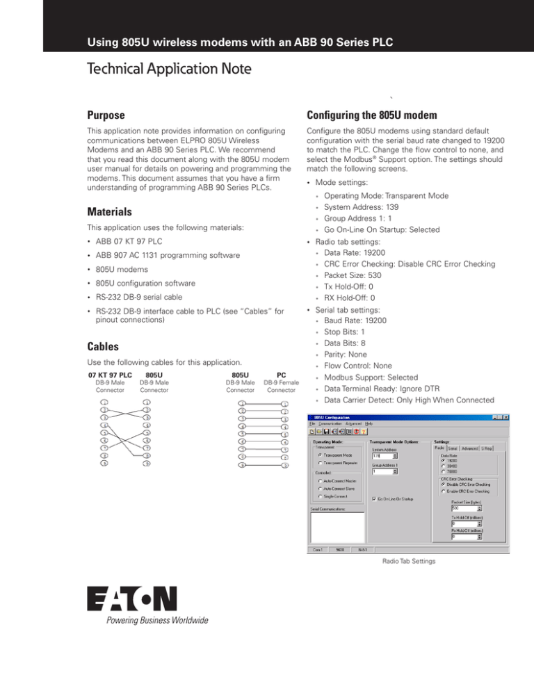
Configure the 805U modems using standard default
configuration with the serial baud rate changed to 19200
to match the PLC. Change the flow control to none, and
select the Modbus® Support option. The settings should
match the following screens.
•
Mode settings:
•
Materials
•
•
This application uses the following materials:
•
•
ABB 07 KT 97 PLC
•
ABB 907 AC 1131 programming software
•
805U modems
•
805U configuration software
•
RS‑232 DB‑9 serial cable
•
RS‑232 DB‑9 interface cable to PLC (see “Cables” for
pinout connections)
Cables
Use the following cables for this application.
07 KT 97 PLC
DB-9 Male
Connector
805U
DB-9 Male
Connector
805U
DB-9 Male
Connector
PC
DB-9 Female
Connector
Operating Mode: Transparent Mode
System Address: 139
Group Address 1: 1
Go On-Line On Startup: Selected
•
Radio tab settings:
• Data Rate: 19200
• CRC Error Checking: Disable CRC Error Checking
• Packet Size: 530
• Tx Hold-Off: 0
• RX Hold-Off: 0
•
Serial tab settings:
• Baud Rate: 19200
• Stop Bits: 1
• Data Bits: 8
• Parity: None
• Flow Control: None
• Modbus Support: Selected
• Data Terminal Ready: Ignore DTR
• Data Carrier Detect: Only High When Connected
Radio Tab Settings
Configuring the PLC
The PLC program used in this application was selected from
the 907 AC 1131 programming software Help File titled
“Creating a project for the controller 07 KT 97,” which can
be found under the Help/Contents File of the ABB software.
After you have created the project and confirmed the Comm
port settings, connect the modems to the PLC and PC
using the cable configuration described earlier and follow
the procedure described in the Help document to program
the PLC.
Once the PLC is programmed, you can toggle the digital
output on the PLC via the 805U modems from the 907 AC
1131 software, as described in the Help File document.
Serial Tab Settings
If you are configuring modems with Hayes commands via a
terminal, the settings are as follows:
B0 C6 E1 Q0 V1 X0 &B2 &C1 &D0 &E0 &G1 &K0 &L1 &M0
&N1 &S139 &U1 \T0
S0:1 S1:50 S2:43 S3:13 S4:10 S5:8 S6:0 S7:5 S8:0 S9:80
S10:1 S11:0 S12:1
S13:0 S14:255 S15:0 S16:0 S17:0 S18:0 S19:3 S20:100
&Z0=
&Z1=
&Z2=
&Z3=
Eaton’s wireless business
www.eaton.com/wireless
North America & Latin America
5735 W. Las Positas Suite 100
Pleasanton, CA 94588
United States
Telephone: +1 925 924 8500
Australia, New Zealand
9/12 Billabong Street
Stafford Queensland 4053
Australia
Telephone: +61 7 3352 8600
Southeast Asia
2 Serangoon North Avenue 5
# 06-01 Fu Yu Building, 554911
Singapore
Telephone: +65 6645 9888
Europe
Hein-Moeller-Straße 7-11
53115 Bonn, Germany
Telephone: +49 228 602 5573
China
955 Shengli Road
East Area of Zhangjiang High-Tech Park
Shanghai, 201201
China
Telephone: +86 21 2899 3600
Eaton
1000 Eaton Boulevard
Cleveland, OH 44122
United States
Eaton.com
© 2014 Eaton
All Rights Reserved
Printed in USA
September 2014
Eaton is a registered trademark.
All other trademarks are property
of their respective owners.


