Technical Data TD032009EN
Effective January 2014
505U-K Wireless I/O
One‑way low‑power transmitter
Description
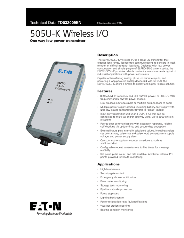
The ELPRO 505U-K Wireless I/O is a small I/O transmitter that
extends long‑range, license-free communications to sensors in local,
remote, or difficult‑to‑reach locations. Designed with low power
consumption and simple plug-in of ELPRO BU-5 battery packs, the
ELPRO 505U-K provides reliable continuity in environments typical of
industrial applications with power constraints.
Capable of transferring analog, pluse, or discrete inputs, and
powering a loop-powered analog device (24 Vdc, 50 mA), the
ELPRO 505U-K offers a simple‑to‑deploy and highly reliable solution.
Features
•
869.525 MHz frequency and 500 mW RF power, or 869.875 MHz
frequency and 5 mW RF power models
•
Link process inputs to single or multiple outputs (peer to peer)
•
Multiple power supply options, including battery-only supply with
ultra-low power consumption (reverts to “sleep” mode)
•
Input-only transmitter unit (2 or 4 DI/PI, 1 AI) that can be
connected to multi‑I/O and/or gateway units, up to 3000 units in
a system
•
Peer-to-peer communications with exception reporting, reliable
self-checking via update time, and secure data encryption
•
External inputs plus internally calculated values, including analog
set point status, pulse rate and pulse total, power/battery supply
voltage, and power supply alarm
•
Can connect to up/down counter transducers, such as
shaft encoders
•
Configurable repeat transmissions to five times for message
reliability
•
Set point, pulse count, and rate available. Additional internal I/O
points provided for health monitoring
Applications
•
High‑level alarms
•
Security gate control
•
Emergency shower notification
•
Flow meter monitoring
•
Storage tank monitoring
•
Pipeline cathodic protection
•
Pump stop-start
•
Lighting bank control
•
Power reticulation relay fault notifications
•
Weather station reporting
•
Bearing condition monitoring
Technical Data TD032009EN
505U-K Wireless I/O
Effective January 2014
Specifications
SPECIFICATION
DESCRIPTION
Transmitter and Receiver
Frequency
868.525 MHz a
869.875 MHz b
Transmit power
500 mW a
5 mW b
Transmission
Frequency modulation (FM)
Modulation
Digital frequency shift key (DFSK)
Channel spacing
250 kHz
Data rate
19.2 kbps with forward error correction
Range (LoS)
6.2 miles (10 km) @ 500 mW a c EIRP
0.62 miles (1 km) @ 5 mW b c EIRP
Antenna connector
Female SMA standard polarity
Internal gas discharger arrestor protection
Input and Output
Digital inputs
TTL voltage 0–1.5 Vdc (on), 3.5–13 Vdc (off)
Surge protected, not isolated, voltage-free/NPN contacts
2 DI (external, status)
Analog inputs
0–24 mA or 0–10V (selectable, over range indication 0–25 mA)
Floating differential inputs, common mode voltage 27V
Resolution 12-bit, accuracy <0.1%
24 Vdc @ 50 mA for external loops provided
Pulse inputs
As per digital input specifications above
Maximum pulse rate 10 kHz (50 kHz possible on PI1 using a
configurable divider)
Pulse width minimum 0.2 ms, volt-free contacts 300 Hz
2 PI (pulse total, count, rate)
Serial Port
RS‑232
9-pin DB‑9 female connector (use for programming only)
Data rate (bps)
9600 bps
Serial settings
8 data bits, 1 stop, no parity
Protocols and Configuration
System address
Configurable system address
Protocols supported
ELPRO WIBnet™ up to four retries, CRC error checking
User configuration
E-series configuration utility
Configurable
Individual I/O mappings, analog and digital debounce, update
parameters
time, analog set points, and sensitivities
Security
64-bit encryption on radio
LED Indication and Diagnostics
LED indication
OK/active, TX/link
Refer to product manual for further information
Reported diagnostics I/O status
General
Size
6.7" x 2.5" x 1.4" (170 mm x 64 mm x 36 mm)
Housing
Powder-coated aluminum
Mounting
Panel mount/connector and cable lead
Terminal blocks
Weatherproof connector with 3.2' (1m) lead
Temperature rating
–40 to +140°F (–40 to +60°C)
Humidity rating
0–99% RH noncondensing
Weight
1 lb (500g)
Power Supply
Nominal supply
6 to 30 Vdc, under/over voltage protection
9 Vdc battery supply
Average current draw 10 mA @ 12 Vdc (idle) + analog loop 2 (internally generated,
24 Vdc/50 mA
Sleep mode 140 μA
Transmit current draw 300 mA @ 12 Vdc
Battery (optional
6 x AA alkaline batteries 9V, up to 1.4‑year service life
ELPRO BU5-2)
depending on input configuration
Enclosure specifications as per 505U-K enclosure
Temperature dependent on battery type used
2
EATON www.eaton.com/wireless
SPECIFICATION
DESCRIPTION
Compliance
EMC
RF (radio)
Safety
CE; EN 301 489
EN 300 220; AS 4268.2; AS 3548
IEC 60950 (RoHS compliant)
NNote: Specifications are subject to change.
a 869.525 MHz available only at 500 mW
c Typical maximum line‑of‑sight range (check
b 869.875 MHz available only at 5 mW
country regulations, single hop, repeaters
will extend)
Accessories
PRODUCT CODE DESCRIPTION
DATA SHEET
Antennas - 900MHz
DG800-1/5
Whip antenna, SMA male, angle bracket,
–2 dBi gain, 3' (1m) or 16.4' (5m) coaxial cable
WH900-SMA
Whip antenna, SMA male, –2 dBi gain
CFD890EL
Dipole antenna, SMA male, mounting bracket,
2 dBi gain, 16' (5m) coaxial cable
SG900EL
Collinear antenna, N-type female, 5 dBi gain
SG900-6
Collinear antenna, N-type female, 8 dBi gain
YU6-870
Yagi antenna, N-type female, 9 dBi gain
YU16-870
Yagi antenna, N-type female, 15 dBi gain
Cables
CC3/10/20-SMA/BNC Coaxial cable kit, 9.8' (3m)/32' (10m)/65' (20m),
N-type to N-type, SMA male/BNC male
CCTAIL-SMA-F/M
CCTAIL-BNC-F/M
SER-DB9
Surge Diverters
CSD-SMA-2500
CSD-N-6000
MA15/D/1/S1
MA15/D/2/S1
IOP32D
Power Supplies
BU5-2
PS-DINAC-12DC-OK
PSG60
Mounting Brackets
BR-YAGI-KIT
BR-COL-KIT
Coaxial cable tail, 24" (600 mm), SMA to
N-type female/male
Coaxial cable tail, 24" (600 mm), BNC to
N-type female/male
Serial RS‑232 cable, DB‑9 male to DB‑9
female, straight through
SMA surge diverter for use with
CC10/CC20-SMA
Coaxial surge diverter, bulkhead N female to
N female
Power supply surge diverter, 110 Vac/15A
Power supply surge diverter, 240 Vac/15A
Signal surge diverter, 2 x 2-wire/1 x 4-wire
TD032046EN
TD032045EN
TD032048EN
TD032049EN
TD032050EN
TD032042EN
TD032051EN
TD032019EN
TD032020EN
TD032021EN
TD032023EN
TD032022EN
TD032026EN
TD032030EN
TD032031EN
TD032029EN
TD032032EN
IP66 battery pack
TD032035EN
DIN rail power supply, 100–250 Vac, 12 Vdc/2.5A TD032033EN
DIN rail power supply, 85–264 Vac, 24 Vdc/2.5A TD032034EN
Mounting bracket kit for Yagi antenna
Mounting bracket kit for collinear antenna
TD032072EN
TD032071EN
Ordering
PRODUCT CODE
505U-K-868-5M
505U-K-868-500M
DESCRIPTION
Transmit only, 2DI, 1 AI,
6–30 Vdc external
Transmit only, 2 DI, 1 AI,
6–30 Vdc external
NNote: Specifications are subject to change.
FREQUENCY
RF POWER
869.875 MHz
5 mW
869.525 MHz
500 mW
Technical Data TD032009EN
505U-K Wireless I/O
Effective January 2014
Eaton’s wireless business
www.eaton.com/wireless
North America & Latin America
5735 W. Las Positas Suite 100
Pleasanton, CA 94588
United States
Telephone: +1 925 924 8500
Australia, New Zealand
9/12 Billabong Street
Stafford Queensland 4053
Australia
Telephone: +61 7 3352 8600
Southeast Asia
2 Serangoon North Avenue 5
# 06-01 Fu Yu Building, 554911
Singapore
Telephone: +65 6645 9888
Europe
Hein-Moeller-Straße 7-11
53115 Bonn, Germany
Telephone: +49 (0) 180 5223822
China
955 Shengli Road
East Area of Zhangjiang High-Tech Park
Shanghai, 201201
China
Telephone: +86 21 2899 3600
Eaton
1000 Eaton Boulevard
Cleveland, OH 44122
United States
Eaton.com
© 2014 Eaton
All Rights Reserved
Printed in USA
Publication No. TD032009EN
January 2014
Eaton is a registered trademark.
All other trademarks are property
of their respective owners.

