Technical Data
Effective February 2014
Aspire RF switch
(no neutral required version)
Project Name:
Prepared By:
Project Number:
Date:
Catalog Number:
Type:
Description
Single pole, 3-way, 4-way
8A, 120V/AC, 60Hz
Incandescent load only
Design features for Aspire RF switch
(no neutral required version)
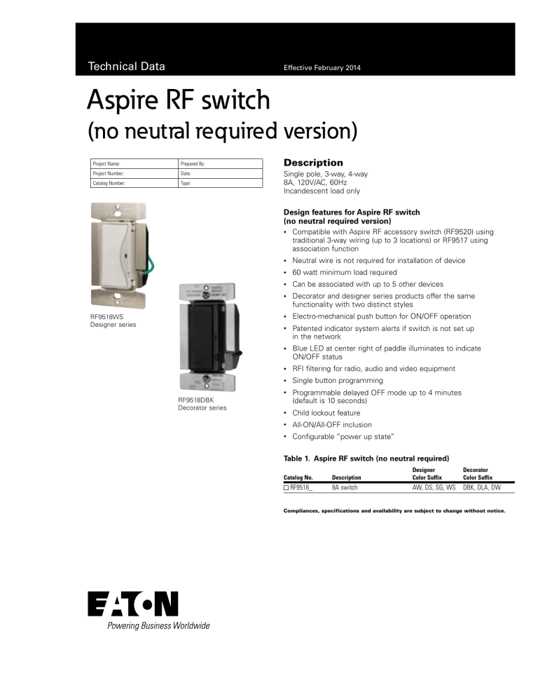
RF9518WS
Designer series
RF9518DBK
Decorator series
•
Compatible with Aspire RF accessory switch (RF9520) using
traditional 3-way wiring (up to 3 locations) or RF9517 using
association function
•
Neutral wire is not required for installation of device
•
60 watt minimum load required
•
Can be associated with up to 5 other devices
•
Decorator and designer series products offer the same
functionality with two distinct styles
•
Electro-mechanical push button for ON/OFF operation
•
Patented indicator system alerts if switch is not set up
in the network
•
Blue LED at center right of paddle illuminates to indicate
ON/OFF status
•
RFI filtering for radio, audio and video equipment
•
Single button programming
•
Programmable delayed OFF mode up to 4 minutes
(default is 10 seconds)
•
Child lockout feature
•
All-ON/All-OFF inclusion
•
Configurable “power up state”
Table 1. Aspire RF switch (no neutral required)
Catalog No.
RF9518_
Description
Designer
Color Suffix
Decorator
Color Suffix
8A switch
AW, DS, SG, WS
DBK, DLA, DW
Compliances, specifications and availability are subject to change without notice.
Technical Data
Aspire RF switch (no neutral required version)
Effective February 2014
Project Name:
Prepared By:
Project Number:
Date:
Catalog Number:
Type:
Applications for switch (no neutral required)
The Aspire RF 8A switch replaces regular switches or dimmers to provide local and remote ON/OFF control for incandescent loads.
Moreover, the Aspire RF switch provides other programmable functions (scenes, events, association, child lockout, etc.) when used with
Aspire RF controllers (RFHDCSG, RFTDCSG, RFTCP, RFUSB-PRO) or other Z-Wave® compliant controllers*. Each switch can be manually
and remotely controlled by commands sent from an Aspire RF controller or other Z-Wave compatible controllers or programs. An Aspire
RF switch utilizes existing 120 V/AC 60Hz standard house wiring and fits in a standard wallbox. No neutral wire required. No new wiring
needed.*Note: some specific Aspire RF features may not be programmable
Table 2. Specifications
Catalog No.
Switch (no neutral required) RF9518
Performance
Testing & Code Compliance
Maximum Amperage: 8A
Minimum Lamp Wattage: Single-location 60W, multi-location 100W
Rating: 120V/AC, 60Hz
Uses 300 Series Z-Wave Chip @ 40Kbs
Derating is required in multi-gang installations (See multi-unit installation chart listed below)
An Aspire RF Z-Wave enabled device must be within 60 feet of another Z-Wave enabled device to participate in a Z-Wave wireless mesh network.
Any one dimmer or switch can be associated with up to 5 devices (dimmers, switches, receptacles, or plug-in modules)
Please reference the Instruction Sheet included with the product for wiring installation. For programming of the device, see the Aspire RF User
Manual, which is provided with either the handheld (RFHDCSG) or tabletop (RFTDCSG) controllers and are also accessible online at
www.cooperwiringdevices.com/AspireRF
cULus Listed 6B28. NOM Certified. Complies with FCC Part 15, Class B. Z-Wave Compliant Certified
Terminations
Switch has four 6” pre-stripped wire leads for line, load, traveller and ground
Material Characteristics
Flammability: Meets UL94 requirements; V2 rated
Temperature Rating: 32°F to 104°F (0°C to 40°C)
2-year limited product warranty
Performance Consideration
Installation & Programming
Warranty
Table 3. Multi-Unit Installation Chart
Catalog No.
1-Gang
2-Gang
3 or more Gangs
RF9518
8A (1000W)
6.6A (800W)
6.6A (800W)
Table 4. Color Ordering Information
For ordering devices, include Catalog No. followed by the Color Suffix: AW (Alpine White), DS (Desert Sand),
Silver Granite (SG), WS (White Satin), DBK (Decorator Black), DLA (Decorator Light Almond), DW (Decorator White).
Designer series color options:
AW
AW
DS
Alpine White
DS
Desert Sand
SG
SG
Silver Granite
WS
WS
White Satin
Decorator series color options:
DBK
DLA
DW
Decorator
Black
Decorator
Light Almond
Decorator
White
Compliances, specifications and availability are subject to change without notice.
2
eaton www.cooperwiringdevices.com
Technical Data
Aspire RF switch (no neutral required version)
Project Name:
Prepared By:
Project Number:
Date:
Catalog Number:
Type:
Effective February 2014
Table 5. Device Configuration Parameters
Parameter
Description
Value range
1
Delayed OFF
*0 to 127
-128 to -1
2
Panic ON time
*0 to 127
-128 to -1
3
Panic OFF time
*0 to 127
-128 to -1
4
Basic set value
Not used
5
Power up state
1=OFF, 2=ON, 3=Last state
6
Panic mode enable
0=OFF, 1=ON
7
Not used
Not used
*The configuration value is a signed single byte number. This value may represent a value with no units or may represent a value such as time. 0 to 127 (decimal) represents 0 to 127
seconds of time. -128 to -1 (negative decimal numbers) represents 128 to 255 seconds as calculated by this formula.
Config value = desired time in seconds (or desired value) -256
For an example of 172 seconds: config value = 172 - 256 = -84 (decimal) or 0xAC (hex)
Table 6. Device Association Information
Association Groups for RF9518
Group 1
5 nodes maximum
Group 2 - 254
0 nodes maximum
Group 255
1 node maximum
Product Dimensions
1.80”
(45.7mm)
1.29”
(32.6mm)
4.20”
(106.6mm)
3.28”
(83.3mm)
2.61”
(66.4mm)
1.36”(34.5mm)
Figure 1. RF9518
Compliances, specifications and availability are subject to change without notice.
eaton www.cooperwiringdevices.com
3
Technical Data
Aspire RF switch (no neutral required version)
Effective February 2014
Project Name:
Prepared By:
Project Number:
Date:
Catalog Number:
Type:
3-Way Location Wiring Diagram
Single-Pole Location Wiring Diagram
Hot
Red
RF SWITCH
(RF9518)
Black
120V AC
Green
Neutral
ACCESSORY
Light Fixture
Blue
Ground
RF Switch (RF9518)
Connects to Power
Accessory Switch (RF9520)
Connects to Light Fixture
White
4-Way Location Wiring Diagram
Red
Hot
Black
Red
Blue
Tag
Green
120V AC
Green
Ground
Neutral
Blue
Blue
Blue
Blue
Green
ACCESSORY
ACCESSORY
White
White
White
RF Switch (RF9518) (3-way location)
Connects to Power
Light Fixture
ACCESSORY
ACCESSORY
Ground
Ground
White
Accessory Switch (RF9520)
(4-way location)
White
White
Accessory Switch (RF9520) (3-way location)
Connects to Light Fixture
NNote: For multi-location control using the RF association function, use
catalog no. RF9517.
Certifications
& Compliances
Catalog No.
•
RF9518
KEY:
cULus
•
NOM
•
FCC
Related Products
Aspire RF controllers
Aspire RF products
Aspire products
RFHDCSG, RFTDCSG, RFWC5WS
RF9534DW, RF9520DW, RFTR9505-T
9566TRWS, 9544DS, 9521WS
Compliances, specifications and availability are subject to change without notice.
4
eaton www.cooperwiringdevices.com
Light Fixture
Technical Data
Aspire RF switch (no neutral required version)
Effective February 2014
Project Name:
Prepared By:
Project Number:
Date:
Catalog Number:
Type:
Electrical Sector
203 Cooper Circle
Peachtree City, GA 30269
United States
Eaton.com
Cooperwiringdevices.com
Electrical Sector
Canada Operations
5925 McLaughlin Road
Mississauga, Ontario, L5R 1B8
Canada
EatonCanada.ca
Cooperwiringdevices.com
Eaton
1000 Eaton Boulevard
Cleveland, OH 44122
United States
Eaton.com
© 2014 Eaton
All Rights Reserved
Printed in USA
Publication No. E125-0123-14
February 2014
Eaton is a registered trademark.
All other trademarks are property
of their respective owners.
Electrical Sector
Mexico Operations
Carr. Tlalnepantla Cuautitlan Km 17.8 s/n
Col. Villa Jardin esq.
Cerrada 8 de Mayo
Cuautitlan, Mexico CP 54800
Mexico
Eaton.mx
Cooperwiringdevices.com


