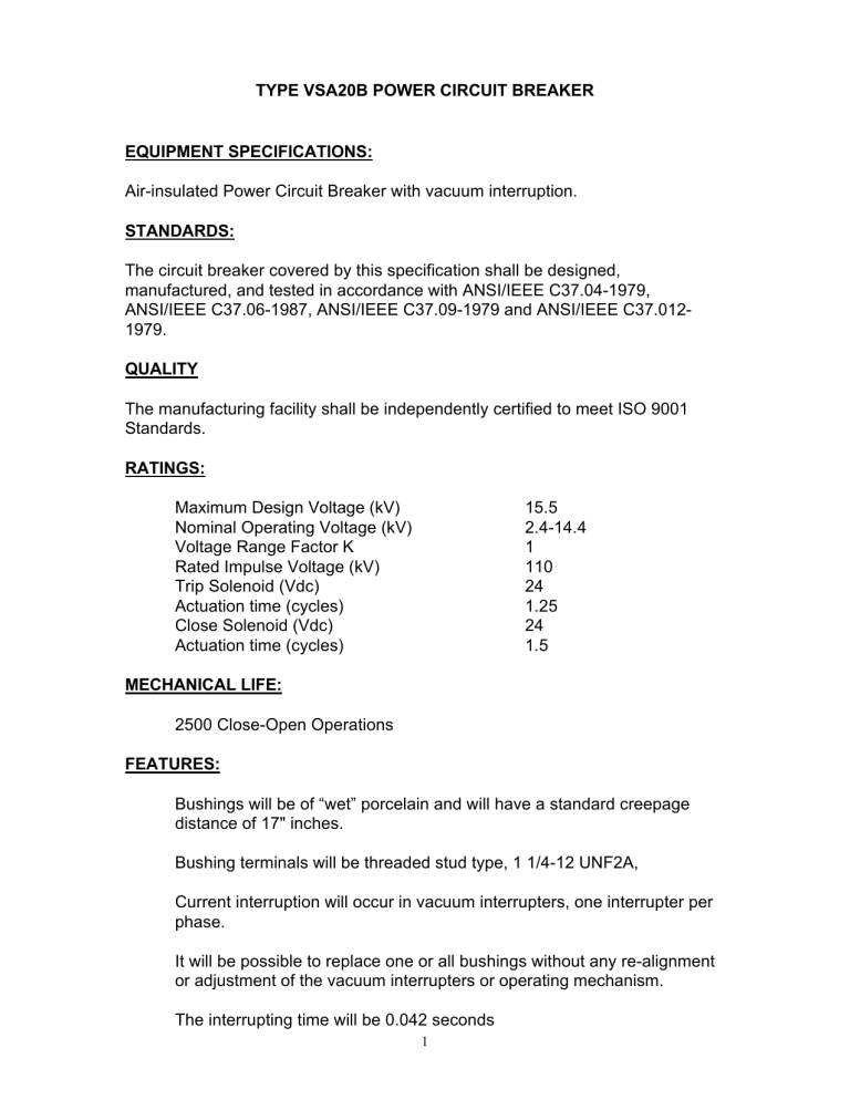
TYPE VSA20B POWER CIRCUIT BREAKER EQUIPMENT SPECIFICATIONS: STANDARDS:

TYPE VSA20B POWER CIRCUIT BREAKER
EQUIPMENT SPECIFICATIONS:
Air-insulated Power Circuit Breaker with vacuum interruption.
STANDARDS:
The circuit breaker covered by this specification shall be designed, manufactured, and tested in accordance with ANSI/IEEE C37.04-1979,
ANSI/IEEE C37.06-1987, ANSI/IEEE C37.09-1979 and ANSI/IEEE C37.012-
1979.
QUALITY
The manufacturing facility shall be independently certified to meet ISO 9001
Standards.
RATINGS:
Maximum Design Voltage (kV)
Nominal Operating Voltage (kV)
Voltage Range Factor K
Rated Impulse Voltage (kV)
Trip Solenoid (Vdc)
Actuation time (cycles)
Close Solenoid (Vdc)
Actuation time (cycles)
MECHANICAL LIFE:
2500 Close-Open Operations
FEATURES:
15.5
2.4-14.4
1
110
24
1.25
24
1.5
Bushings will be of “wet” porcelain and will have a standard creepage distance of 17" inches.
Bushing terminals will be threaded stud type, 1 1/4-12 UNF2A,
Current interruption will occur in vacuum interrupters, one interrupter per phase.
It will be possible to replace one or all bushings without any re-alignment or adjustment of the vacuum interrupters or operating mechanism.
The interrupting time will be 0.042 seconds
1
Resistance-type heaters will be provided in the interrupter and operating mechanism cabinets, to prevent moisture condensation.
The breaker will be shipped mounted in a substation mounting frame.
The mounting frame extension will have a ground pad which will accommodate two No. 2/0 to 250 MCM conductors
Sensing bushing current transformers, 2000:1 ratio, for use with an electronic reclosing breaker, will be mounted internally in the breaker on bushings 1, 3, and 5.
A 4 - digit counter will be provided in the operating mechanism.
The breaker will use a motor operator to charge opening and closing springs; solenoids will be used for the tripping and closing operations.
A contact position indicator, externally visible, will be provided.
Separate external pull rings will be provided to manually trip and close the breaker.
A spring operator condition indicator will be provided to indicate whether the closing springs are energized. The indicator consists of a mechanical flag for indication and will be visible from the front of the operator cabinet.
The breaker will be capable of manual trip and manual close on a maximum fault. Closing springs can be charged manually by means of a crank (150 turns), through a gear box.
SPRING CHARGING MOTOR:
Operating voltage (Vac)
Voltage Range (Vac)
Maximum Current RMSA (amperes)
Steady State Current (amperes)
Motor Running Time (cycles)
CONTROLS:
STANDARD
240
160-257
13
8
40
ACCESSORY
120
90-127
18
9
40
The breaker will be capable of operation with any of the following: Form 3, Form
3A, Form 4A, or Form 4C Type ME Breaker control.
2
rcn5/14/97
3


