Loadbreak
Connectors
CA650074EN
Effective November 2015
Supersedes 500-26 May 2008
COOPER POWER
SERIES
200 A 25 kV class loadbreak bushing
insert
General
Eaton's Cooper Power™ series 25 kV bushing
insert threads into a universal bushing well and
uses a patented design with an all copper current
path. The uncomplicated nature of the current path
design delivers superior, reliable performance.
Latch indicator ring
The latch indicator ring, located on the
circumference of the bushing's collar, eliminates
the guesswork of loadbreak elbow installation on
the bushing insert. The bright yellow ring provides
immediate feedback to determine if the elbow is
properly installed on the insert. If the yellow ring
is completely covered by the loadbreak elbow, it is
fully latched. If the ring is visible, the elbow can be
installed correctly before any problems can occur.
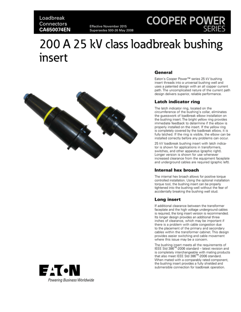
25 kV loadbreak bushing insert with latch indicator is shown for applications in transformers,
switches, and other apparatus (graphic right).
Longer version is shown for use whenever
increased clearance from the equipment faceplate
and underground cables are required (graphic left).
Internal hex broach
The internal hex broach allows for positive torque
controlled installation. Using the optional installation
torque tool, the bushing insert can be properly
tightened into the bushing well without the fear of
accidentally breaking the bushing well stud.
Long insert
If additional clearance between the transformer
faceplate and the high voltage underground cables
is required, the long insert version is recommended.
Its longer design provides an additional three
inches of clearance, which may be important if
there is a problem with cable congestion due
to the placement of the primary and secondary
cables within the transformer cabinet. This design
provides easier switching and cable movement
where this issue may be a concern.
The bushing insert meets all the requirements of
IEEE Std 386™-2006 standard – latest revision and
is completely interchangeable with mating products
that also meet IEEE Std 386™-2006 standard.
When mated with a comparably rated component,
the bushing insert provides a fully shielded and
submersible connection for loadbreak operation.
Catalog Data CA650074EN
200 A 25 kV class loadbreak bushing insert
Effective November 2015
BLUE TAB
Indicates latch indicator ring.
DRAIN WIRE TABS
Three tabs molded into a semi-conductive
shield for the attachment of a drain wire to
maintain deadfront safety.
COPPER KNURLED PISTON
Fault activated copper knurled piston is
forced forward by gas pressure
generated during fault close to engage
elbow probe. Knurled piston contact
provides reliable current interchange
and locks piston in place during
switching operations.
FINGER CONTACTS
The copper finger
contacts are threaded
into the copper piston.
CONTACT TUBE
Molded thermoplastic
contact tube ensures
reliable switching and
fault close performance.
THREADED BASE
3/8"-16 UNC
Copper threads
provide connection
to bushing well
stud.
INSULATION
High quality, peroxide-cured EPDM
rubber formulated, mixed and molded
in-house for consistent and reliable
field performance.
ARC SNUFFER ASSEMBLY
Arc-ablative plastic produces
arc extinguishing gas during
loadbreak switching operations.
HEX BROACH
5/16” hex broach permits consistent
installation with torque tool.
LATCH INDICATOR RING
Molded-in bright yellow ring
eliminates elbow installation
guesswork by assuring a quality
connection.
SEMI-CONDUCTIVE SHIELD
High quality peroxide-cured
EPDM rubber provides
protective deadfront shield that
meets requirements of IEEE Std
592™-2007 standard.
Figure 1. Bushing insert cutaway illustrates uncomplicated nature and dependability of current path.
A
B
S1
S2
25 kV
Short
(in/mm)
25 kV
Long
(in/mm)
7.11
9.94
180.5
252.5
3.16
5.99
80.2
152.2
0.76
0.76
19.3
19.3
7.14
9.97
181.4
253.2
Figure 2. Bushing insert profile and stacking dimensions, as referenced in Figure 13
IEEE Std 386™-2006 standard.
2
www.eaton.com/cooperpowerseries
Catalog Data CA650074EN
200 A 25 kV class loadbreak bushing insert
Effective November 2015
Installation
Ordering information
No special tools are necessary. The insert can be installed by hand
or with the assistance of a torque tool. Using the hex-broached
base (see Figure 2) and the LBI installation torque tool (see Figure
4), consistent installation can be easily achieved. Refer to Service
Information MN650013EN 200 A 15 and 25 kV Class Loadbreak
Bushing Insert Installation Instructions for details.
The standard insert kit is packaged in a sealed heavy duty
polyethylene bag. Twenty-five individual kits are packed to a single
multi-pak box. The long version is packed 15 kits to a box. Other
packaging options are also available. Please contact the factory for
the appropriate part numbers. To order the 25 kV Class Loadbreak
Bushing Kit, refer to Table 3.
Each kit contains:
Production tests
Tests conducted in accordance with IEEE Std 386™-2006 standard:
•
•
AC 60 Hz 1 Minute Withstand
• 40 kV
Minimum Corona Voltage Level
• 19 kV
•
Loadbreak Bushing Insert
•
Shipping Cap (not for energized operation)
•
Silicone Lubricant
•
Installation Instruction Sheet
Table 3. Loadbreak Bushing Insert Kit
Tests conducted in accordance with Eaton requirements:
Description
Catalog Number
•
Physical Inspection
Loadbreak Bushing Insert Standard length
LBI225
•
Periodic Dissection
Periodic X-ray Analysis
Loadbreak Bushing Insert Long Version
LBI225L
•
Installation Torque Tool
LBITOOL
Table 1. Voltage Ratings and Characteristics
Description
kV
Standard Voltage Class
25
Maximum Rating Phase-to-phase
26.3
Maximum Rating Phase-to-ground
15.2
AC 60 Hz 1 Minute Withstand
40
DC 15 Minute Withstand
78
BIL and Full Wave Crest
125
Minimum Corona Voltage Level
19
Voltage ratings and characteristics are in accordance with IEEE Std 386™-2006 standard.
Table 2. Current Ratings and Characteristics
Description
Amperes
Continuous
200 A rms
Switching
10 operations at 200 A rms at 26.3 kV
Fault Closure
10,000 A rms symmetrical at 26.3 kV for 0.17 s after 10
switching operations
Short Time
10,000 A rms symmetrical for 0.17 s
Figure 3. Insert installation torque tool.
3,500 A rms symmetrical for 3.0 s
Current ratings and characteristics are in accordance with IEEE Std 386™-2006 standard.
www.eaton.com/cooperpowerseries
3
Catalog Data CA650074EN
200 A 25 kV class loadbreak bushing insert
Effective November 2015
Eaton
1000 Eaton Boulevard
Cleveland, OH 44122
United States
Eaton.com
Eaton’s Cooper Power Systems Division
2300 Badger Drive
Waukesha, WI 53188
United States
Eaton.com/cooperpowerseries
© 2015 Eaton
All Rights Reserved
Printed in USA
Publication No. CA650074EN
Eaton is a registered trademark.
All other trademarks are property
of their respective owners.
For Eaton's Cooper Power series product
information call 1-877-277-4636 or visit:
www.eaton.com/cooperpowerseries.


