Loadbreak Connectors
Catalog Data
CA650070EN
Effective December 2015
Supersedes 500-111 July 2012
COOPER POWER
SERIES
25 kV class fused loadbreak elbow
connector
General
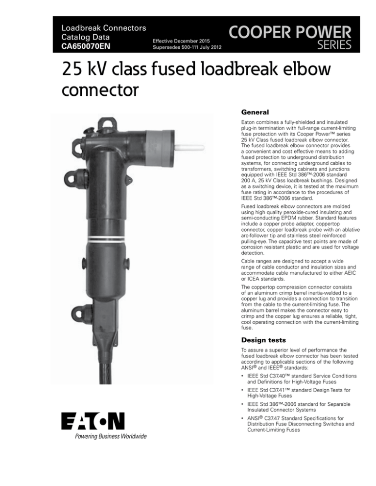
Eaton combines a fully-shielded and insulated
plug-in termination with full-range current-limiting
fuse protection with its Cooper Power™ series
25 kV Class fused loadbreak elbow connector.
The fused loadbreak elbow connector provides
a convenient and cost effective means to adding
fused protection to underground distribution
systems, for connecting underground cables to
transformers, switching cabinets and junctions
equipped with IEEE Std 386™-2006 standard
200 A, 25 kV Class loadbreak bushings. Designed
as a switching device, it is tested at the maximum
fuse rating in accordance to the procedures of
IEEE Std 386™-2006 standard.
Fused loadbreak elbow connectors are molded
using high quality peroxide-cured insulating and
semi-conducting EPDM rubber. Standard features
include a copper probe adapter, coppertop
connector, copper loadbreak probe with an ablative
arc-follower tip and stainless steel reinforced
pulling-eye. The capacitive test points are made of
corrosion resistant plastic and are used for voltage
detection.
Cable ranges are designed to accept a wide
range of cable conductor and insulation sizes and
accommodate cable manufactured to either AEIC
or ICEA standards.
The coppertop compression connector consists
of an aluminum crimp barrel inertia-welded to a
copper lug and provides a connection to transition
from the cable to the current-limiting fuse. The
aluminum barrel makes the connector easy to
crimp and the copper lug ensures a reliable, tight,
cool operating connection with the current-limiting
fuse.
Design tests
To assure a superior level of performance the
fused loadbreak elbow connector has been tested
according to applicable sections of the following
ANSI® and IEEE® standards:
•
IEEE Std C37.40™ standard Service Conditions
and Definitions for High-Voltage Fuses
•
IEEE Std C37.41™ standard Design Tests for
High-Voltage Fuses
•
IEEE Std 386™-2006 standard for Separable
Insulated Connector Systems
•
ANSI® C37.47 Standard Specifications for
Distribution Fuse Disconnecting Switches and
Current-Limiting Fuses
Catalog Data CA650070EN
25 kV class fused loadbreak elbow connector
Effective December 2015
PULLING
EYE
SEMI-CONDUCTING
LOADBREAK
SHIELD
PROBE
ARC
FOLLOWER
SEMI-CONDUCTIVE
INSERT
DRAIN WIRE TAB
PROBE ADAPTER
EPDM
INSULATION
CURRENT-LIMITING FUSE
LOADBREAK BAND
TEST
POINTS
COPPERTOP
CONNECTOR
DRAIN WIRE TABS
Figure 1. 25 kV Class fused loadbreak elbow connector cutaway illustrates design features.
2
www.eaton.com/cooperpowerseries
Catalog Data CA650070EN
25 kV class fused loadbreak elbow connector
Effective December 2015
5.27”
(134 mm)
4.55”
(116 mm)
1.75”
(44 mm)
3.86”
(98 mm)
3.25”
(83 mm)
NNote: Dimensions given are for
reference only.
20.30”
(516 mm)
Figure 2. 25 kV Class fused loadbreak elbow connector profile and stacking dimensions shown.
www.eaton.com/cooperpowerseries
3
Catalog Data CA650070EN
25 kV class fused loadbreak elbow connector
Effective December 2015
Installation
METAL NEUTRAL
OR SHIELD
Cable stripping and scoring tools available from
various tool manufacturers are recommended for
use when installing fused loadbreak elbows. After
preparing the cable, the cable housing is pushed
onto the cable. The current-limiting fuse is threaded
into the coppertop connector using the supplied hex
wrench. The probe adapter and elbow housing are
installed and loadbreak probe threaded into the probe
adapter. Use a clampstick to perform loadmake and
loadbreak operations. Refer to installation instructions,
MN650014EN.
Production tests
Tests conducted in accordance with IEEE Std 386™2006 standard:
•
DIAMETER OVER
OUTER JACKET
Minimum Corona Voltage Level
• 19 kV
•
Test Point Voltage Test
Physical Inspection
•
Periodic Dissection
•
Periodic Fluoroscopic Analysis
CONDUCTOR
INSULATION
CONDUCTOR
SHIELD
Figure 3. Illustration showing typical construction of medium voltage underground cable.
Ordering information
The fused loadbreak elbow connector, elbow/cable housing kits
are packaged in individual corrugated cardboard cartons. Each kit
contains:
Tests conducted in accordance with Eaton requirements:
•
INSULATION
SHIELD
OUTER JACKET
AC 60 Hz 1 Minute Withstand
• 40 kV
•
DIAMETER OVER
INSULATION
Table 1. Voltage Ratings and Characteristics
Description
kV
Standard Voltage Class
Maximum Rating Phase-to-Phase
Maximum Rating Phase-to-Ground
AC 60 Hz 1 Minute Withstand
DC 15 Minute Withstand
BIL and Full Wave Crest
Minimum Corona Voltage Level
25
15.2
15.2
40
78
125
19
Voltage ratings and characteristics are in accordance with IEEE Standard 386™-2006 standard.
Table 2. Current Ratings and Characteristics
Description
Amperes
Continuous
Switching
Fault Closure
Fuse rating
10 operations at fuse current rating at 15.5 kV
10,000 A rms symmetrical at 15.5 kV after 10 switching
operations
•
Fused Elbow, Cable Housing
•
Fused Elbow, Elbow Housing
•
Coppertop Compression Connector
•
Loadbreak Probe
•
Probe Adapter and Set Screws
•
Probe Installation Tool
•
1/8” Hex Wrench
•
Silicone Lubricant
•
Installation Instruction Sheet
NNote: Current-Limiting fuses sold separately. See Tables 6 and 7 for fuse
recommendations and Table 5 for electrical ratings and catalog number
information.
To order a 25 kV Class fused loadbreak elbow connector kit follow
the easy steps below.
STEP 1: Determine the cable’s diameter over the electrical insulation
as shown in Figure 3 (including tolerances) from cable manufacturer.
Then identify a cable range from Table 3 that brackets the minimum
and maximum insulation diameters. Select the CABLE RANGE
CODE from the far right column.
STEP 2: Identify the conductor size and type in Table 4 and select
the CONDUCTOR CODE from the far right column.
For an elbow kit without a compression connector, use “00” for the
conductor code.
STEP 3: For a fused loadbreak elbow and cable housing kit order:
LFEP225TFEC
CABLE RANGE
CODE
CONDUCTOR
CODE
AT
Table 3. Cable Range for Loadbreak Elbow
4
www.eaton.com/cooperpowerseries
Inches
Millimeters
Cable Range Code
0.610” - 0.820”
15.5 - 20.8
A
0.740” - 0.980”
18.8 - 24.9
B
0.910” - 1.180”
23.1 - 29.9
C
Catalog Data CA650070EN
25 kV class fused loadbreak elbow connector
Effective December 2015
EXAMPLE: Select a fused elbow probe and conductor housing kit
for 1/0 compressed stranded with a minimum insulation diameter of
0.830” (21.0 mm) and a maximum diameter of 0.890” (22.6 mm).
STEP 1: From Table 3, identify the cable range 0.740”—0.980” (18.8
mm - 24.9 mm) and select the “B” CABLE RANGE CODE.
Table 4. Conductor Size and Type
Class B Stranded or
Compressed
AWG
Compact or Solid
mm2
AWG
mm2
CONDUCTOR
CODE
35
—
50
70
—
95
120
#2
#1
1/0
2/0
3/0
4/0
250
—
35
—
50
70
—
95
120
—
00
03
04
05
06
07
08
09
10
No Connector
STEP 2: The conductor size is a 1/0 and the type is compressed.
From Table 4, under the column “Class B Stranded or Compressed”
identify 1/0 and select the “06” conductor code.
STEP 3: Order catalog number.
LFEP225TFECB06AT
#2
#1
1/0
2/0
3/0
4/0
250*
* Compressed stranding only.
NNote: Coppertop compression connector may be used on both aluminum and
copper cable conductors.
Table 5. Fused Loadbreak Elbow Connector
Fuse Electrical Ratings and Catalog Numbers
Nominal
System
Voltage
Class - kV
25
Nominal Fuse
Voltage
Rating kV
15.5
Maximum Continuous Current
Nominal Fuse
Current rating
in Amperes
Fuse Catalog
Number
25°C
40°C
65°C
Minimum Melt
I²t (A²s)
Maximum Total
I²t (A²s)
6
FEF155A006
8.5
8.3
8.0
710
3,800
8
FEF155A008
11.7
11.3
10.9
1,000
5,435
10
FEF155A010
14.4
13.9
13.5
1,200
5,500
12
FEF155A012
16.0
15.5
15.0
1,200
5,500
18
FEF155A018
21.1
20.4
19.7
1,500
7,800
20
FEF155A020
24.6
23.7
23.0
2,425
12,000
200 A shorting bar (solid link)
The 200 A fused loadbreak elbow connector shorting bar is used
for temporary restoration of service when a standard fuse is not
available and can also be used during fault locating and grounding.
Catalog FESBA kit contains:
(1) Shorting Bar (solid Link)
(1) 3/16” re-usable hex wrench
(1) 1/8” re-usable hex wrench
(25) Adapter set screws
(5) Wire probe wrenches
(1) Bleeder strap
(1) Re-usable caution tag with clasp
(1) Hard plastic carrying case
(1) Installation Instruction Sheet
Figure 4. Shorting bar kit, catalog FESBA
www.eaton.com/cooperpowerseries
5
Catalog Data CA650070EN
25 kV class fused loadbreak elbow connector
Effective December 2015
Table 6. Recommended Fuse Ratings for Single- and Three-Phase Applications
Nominal Fuse Rated Voltage - 8.3 kV
Transformer Single-Phase Voltage Rating (kV) - Phase-to-Ground
2.4 kV
4.16 kV
4.8 kV
6.93 - 7.2 kV
1ø kVA
A
B
A
B
A
B
A
B
7.62 & 7.97 kV
A
B
12 & 12.47 kV
A
B
13.2 kV
A
B
13.8 kV
A
B
14.4 kV
A
B
10
15
25
37.5
50
75
100
167
250
333
500
—
—
—
—
8
12
18
25
—
—
—
—
—
—
—
—
8
10
18
—
—
—
—
—
—
—
—
8
10
18
—
—
—
—
—
—
—
—
8
10
18
—
—
—
—
—
—
—
—
—
12
20
—
—
—
—
8
12
20
25
40
—
—
—
—
—
6
10
20
25
40
—
—
—
—
—
—
—
—
8
10
18
20
30
—
—
—
—
6*
6
10
18
20
30
—
—
—
—
—
—
—
—
10
12
20
30
—
—
—
—
—
6
8
12
20
30
40
—
—
—
—
—
—
—
—
10
12
25
40
—
—
—
Nominal Fused Rated Voltage - 15.5 kV
6*
6*
6
8
12
20
30
—
—
—
—
6*
6*
6
8
10
18
25
40
—
—
—
6*
6*
6*
6
6
10
18
—
—
—
—
6*
6*
6*
6*
6
8
12
—
—
—
—
6*
6*
6*
6
6
10
18
—
—
—
—
6*
6*
6*
6*
6
8
10
20
—
—
—
Nominal Fuse Rated Voltage - 8.3 kV
Transformer Three-Phase Voltage Rating (kV) - Phase-to-Phase
2.4 kV
4.16 kV
4.8 kV
8.32 kV
3ø kVA A
B
A
B
A
B
A
B
12.47 kV
A
B
13.2 to 14.4 kV
A
B
20.8 kV
A
B
22.9 - 24.9 kV
A
B
30
45
75
112.5
150
225
300
500
750
1000
1500
—
—
—
—
—
12
18
30
—
—
—
—
—
—
—
8
12
18
30
40
—
—
—
—
—
—
8
12
12
18
—
—
—
6*
6*
6
8
10
12
18
—
—
—
—
—
—
—
6
8
10
18
—
—
—
—
10
12
20
40
—
—
—
—
—
—
—
12
20
30
—
—
—
—
—
—
—
—
—
8
12
20
25
40
—
—
—
—
—
6
10
20
28
40
—
—
—
—
—
—
—
—
10
18
20
40
—
—
—
—
—
6
8
18
25
30
—
—
—
—
—
—
—
—
—
10
12
20
25
40
—
—
—
6*
6
8
12
20
25
40
—
—
—
—
Nominal Fused Rated Voltage - 15.5 kV
6*
6*
6
8
12
20
25
40
—
—
—
6*
6*
6*
8
12
18
25
40
—
—
—
6*
6*
6*
6
8
10
12
—
—
—
—
* Fuse allows more than 300% of the transformer rating.
Notes:
• Fuse selection is based on the continuous current rating of the fuses at 40°C
• Fuses in listed Column A allow between 1.4 and 2 times the rated current of the transformer; those listed in Column B, allow 2-3 times the rated
current of the transformer.
• Recommended fuses meet inrush criteria of 12 times transformer full load current for 0.1 second and 25 times full load current for 0.01 second.
Fuses also meet cold load pickup criteria of 6 times transformer full load current for 1 second and 3 times full load current of 10 seconds.
• For three-phase applications, recommendations are limited to GRDY-GRDY transformers with no more than 50% delta connected secondary load,
along with certain other assumptions. It is common practice to use line-to-ground rated fuses.
Table 7. Recommended Fuse Ratings for Three-Phase Delta Applications
Transformer Three-Phase Voltage Rating (kV) - Phase-to-Phase
Nominal Fuse Rated Voltage - 8.3 kV
2.4 kV
4.16 kV
4.8 kV
8.32 kV
3ø kVA
30
45
75
112.5
150
225
300
500
750
1000
1500
A
10
12
20
40
—
—
—
—
—
—
—
B
12
20
30
—
—
—
—
—
—
—
—
A
—
8
12
20
25
40
—
—
—
—
—
B
6
10
20
28
40
—
—
—
—
—
—
A
—
—
10
18
20
40
—
—
—
—
—
B
6
8
18
25
30
—
—
—
—
—
—
A
—
—
—
10
12
20
25
40
—
—
—
Nominal Fuse Rated Voltage - 15.5 kV
12.47 kV
13.2 to 14.4 kV
B
6*
6
8
12
20
25
40
—
—
—
—
A
—
—
—
—
—
12
18
—
—
—
—
B
6*
6*
6
8
12
20
20
—
—
—
—
A
—
—
—
—
8
12
18
—
—
—
—
B
6*
6*
6*
8
12
18
201
—
—
—
—
* Fuse allows more than 300% of the transformer rating.
1 20 A @ 14.4 kV only.
Notes:
• Fuse selection is based on the continuous current rating of the fuses at 40°C
• Fuses in listed Column A allow between 1.4 and 2 times the rated current of the transformer; those listed in Column B, allow 2-3 times the rated
current of the transformer.
• Recommended fuses meet inrush criteria of 12 times transformer full load current for 0.1 second and 25 times full load current for 0.01 second.
Fuses also meet cold load pickup criteria of 6 times transformer full load current for 1 second and 3 times full load current of 10 seconds.
6
www.eaton.com/cooperpowerseries
Catalog Data CA650070EN
25 kV class fused loadbreak elbow connector
Effective December 2015
Table 8. Replacement Fused Loadbreak Elbow Connector
Table 9. Replacement Parts
Conductor Size
Description
Catalog Number
Concentric or
Compressed
Compact or Solid
Loadbreak Probe Installation Tool
2602733A01
Probe Kit (includes Probe, Installation Tool, Silicone Lubricant,
Installation Instruction Sheet)
PK225
Probe Adapter Kit (Includes Adapter, (2) Set Screws and 1/8”
Hex Wrench
FEADPT
Fuse Replacement Wrench Kit (includes Probe Adapter, (2) Set
Screws, 1/8” Hex Wrench, (2) 3/16” Hex Wrenches, (2) Probe
Installation Tools
FEWKIT
2603393A03
2605670A02M
2639992A01
AWG
mm2
Catalog
Number
#2
35
FECC2C03T
#1
—
FECC2C04T
—
1/0
50
FECC2C05T
1/0
50
2/0
70
FECC2C06T
2/0
70
3/0
—
FECC2C07T
3/0
—
4/0
95
FECC2C08T
Silicone Grease
0.175 oz tube (5 grams)
5.3 oz tube (150 grams)
4/0
95
—
—
FECC2C09T
Test Point Cap
250*
120
—
—
FECC2C10T
AWG
mm2
#2
35
#1
* Compressed stranding only.
NNote: Coppertop compression connector may be used on both aluminum and
copper cable conductors.
www.eaton.com/cooperpowerseries
7
Catalog Data CA650070EN
25 kV class fused loadbreak elbow connector
Effective December 2015
Eaton
1000 Eaton Boulevard
Cleveland, OH 44122
United States
Eaton.com
Eaton’s Cooper Power Systems Division
2300 Badger Drive
Waukesha, WI 53188
United States
Eaton.com/cooperpowerseries
© 2015 Eaton
All Rights Reserved
Printed in USA
Publication No. CA650070EN
Eaton is a registered trademark.
All other trademarks are property
of their respective owners.
For Eaton's Cooper Power series product
information call 1-877-277-4636 or visit:
www.eaton.com/cooperpowerseries.

