31M Series mVEC
Multiplexed Power Distribution Module
Multiplexed Vehicle Electrical Center (mVEC)
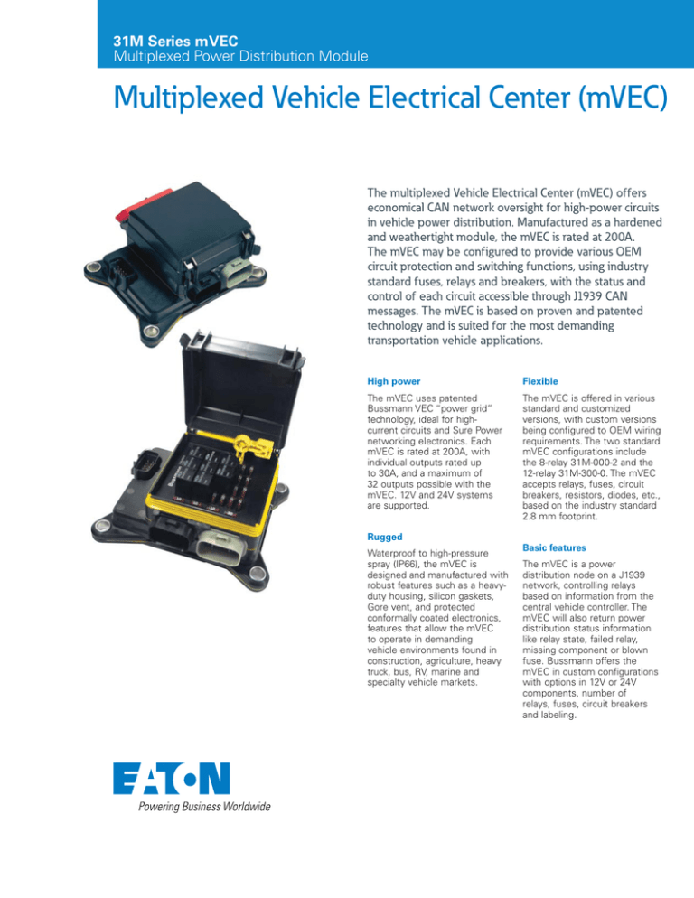
The multiplexed Vehicle Electrical Center (mVEC) offers
economical CAN network oversight for high-power circuits
in vehicle power distribution. Manufactured as a hardened
and weathertight module, the mVEC is rated at 200A.
The mVEC may be configured to provide various OEM
circuit protection and switching functions, using industry
standard fuses, relays and breakers, with the status and
control of each circuit accessible through J1939 CAN
messages. The mVEC is based on proven and patented
technology and is suited for the most demanding
transportation vehicle applications.
High power
Flexible
The mVEC uses patented
Bussmann VEC “power grid”
technology, ideal for highcurrent circuits and Sure Power
networking electronics. Each
mVEC is rated at 200A, with
individual outputs rated up
to 30A, and a maximum of
32 outputs possible with the
mVEC. 12V and 24V systems
are supported.
The mVEC is offered in various
standard and customized
versions, with custom versions
being configured to OEM wiring
requirements. The two standard
mVEC configurations include
the 8-relay 31M-000-2 and the
12-relay 31M-300-0. The mVEC
accepts relays, fuses, circuit
breakers, resistors, diodes, etc.,
based on the industry standard
2.8 mm footprint.
Rugged
Waterproof to high-pressure
spray (IP66), the mVEC is
designed and manufactured with
robust features such as a heavyduty housing, silicon gaskets,
Gore vent, and protected
conformally coated electronics,
features that allow the mVEC
to operate in demanding
vehicle environments found in
construction, agriculture, heavy
truck, bus, RV, marine and
specialty vehicle markets.
Basic features
The mVEC is a power
distribution node on a J1939
network, controlling relays
based on information from the
central vehicle controller. The
mVEC will also return power
distribution status information
like relay state, failed relay,
missing component or blown
fuse. Bussmann offers the
mVEC in custom configurations
with options in 12V or 24V
components, number of
relays, fuses, circuit breakers
and labeling.
Specifications
Options
Capacity
Operating temperature ratings
Input
•
•
200A maximum rating
–40°C to 85°C
•
30A per output pin
Ingress protection
•
Maximum of 12 relays
and/or 32 fuses, or various
combinations thereof (unique
design configurations may
be required)
IP66 compliant
Foot torque rating
•
60 in-lbs without
compression limiters
•
200 to 300 in-lbs with
compression limiters
Materials
•
Housing and connector
cavities: 94V-0 rated
thermoplastic
•
Internal power grid:
tin-plated copper
•
CAN circuit board:
conformally coated
•
•
Connections
Output: Standard Bussmann
VEC connectors
•
8-way, colored/keyed,
sealed connectors
•
30A maximum per terminal
•
Accepts Packard Metri-Pack
280 Series terminals
(tanged/tangless)
Studded input option: Supports
two M8 input power studs for
DC power into the VEC power
grid (100A maximum per stud)
Connectorized: Accepts
up to two Cooper Bussmann
32004 VEC connectors (two
terminal, colored/keyed,
sealed connectors)
1. Mounting: Compression
limiters on mounting feet
2. Labeling to customer
specifications
3. Stuffed (with/without
components, including,
but not limited to, fuses,
relays, diodes, circuit
breakers, fuse puller)
4. Customized circuit layouts,
standard and custom
CAN messages
60A maximum per terminal,
providing power to the VEC
Power Grid; uses Packard
800 series terminals
5. Cover marking: Laser etching
inside, outside or both
CAN
•
Uses AMP SSC 12-position
sealed connector
•
CAN connector provides CAN
signaling, power, ground,
addressing, auxiliary relay
control and reserve connections
to mVEC “smart” layer
Dimensions in Inches (mm)
M6 or M8 Input Stud
(Stainless or Plated Steel)
Studded Input
Shown, Cover
Not Shown
Assembly Shown with Standard
Brass Grommet. 11.8 ± 0.25. ID
M11 or 7/16 Fastener Suggested
Maximum Fastener Torque
80 Nm or 60 ft-lbs
1.16
(29.5)
4.72
(120.0)
Gasket Plug (Optional)
Assembly Shown with Stainless
Steel Compression Limiter
(Optional) (4) PLCS. 8.40ø ID M8 or
5/16 Fastener Suggested Maximum
Mounting Torque 400 Nm or 300 ft-lbs
Shown with cover
in closed position
Connector
Lock Feature
6.10
(155.0)
Yellow
Silicone Gasket
2.57
(65.4)
3.54
(90.0)
Max.
1.52
(38.6)
0.50 (12.8)
Eaton
Controls and Power Conversion Division
10955 SW Avery Street
Tualatin, OR 97062
United States
Cooperindustries.com/CPCD
Eaton.com
© 2013 Eaton
All Rights Reserved
Printed in USA
Publication No. PA070004EN / Z13687
May 2013
Eaton is a registered trademark.
All other trademarks are property
of their respective owners.


