GUSC Series Installation & Maintenance Information 1712 ApplicAtion
advertisement
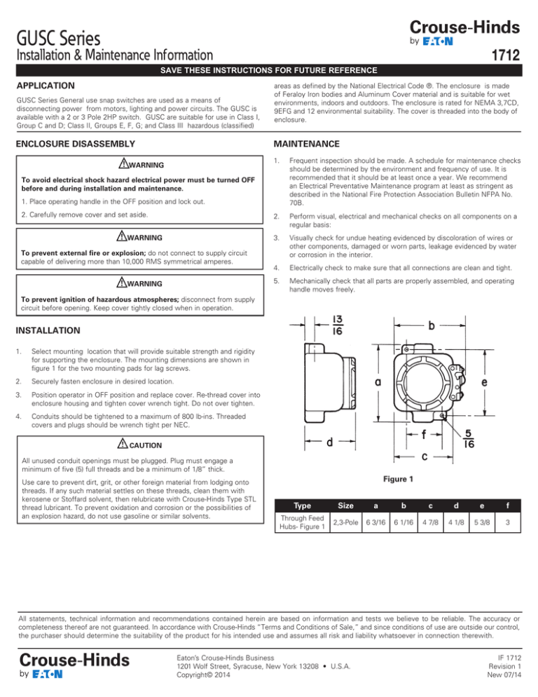
GUSC Series Installation & Maintenance Information 1712 SAVE THESE INSTRUCTIONS FOR FUTURE REFERENCE Application GUSC Series General use snap switches are used as a means of disconnecting power from motors, lighting and power circuits. The GUSC is available with a 2 or 3 Pole 2HP switch. GUSC are suitable for use in Class I, Group C and D; Class II, Groups E, F, G; and Class III hazardous (classified) ENCLOSURE DISASSEMBLY areas as defined by the National Electrical Code ®. The enclosure is made of Feraloy Iron bodies and Aluminum Cover material and is suitable for wet environments, indoors and outdoors. The enclosure is rated for NEMA 3,7CD, 9EFG and 12 environmental suitability. The cover is threaded into the body of enclosure. MAINTENANCE WARNING 1. Frequent inspection should be made. A schedule for maintenance checks should be determined by the environment and frequency of use. It is recommended that it should be at least once a year. We recommend an Electrical Preventative Maintenance program at least as stringent as described in the National Fire Protection Association Bulletin NFPA No. 70B. 2. Perform visual, electrical and mechanical checks on all components on a regular basis: 3. Visually check for undue heating evidenced by discoloration of wires or other components, damaged or worn parts, leakage evidenced by water or corrosion in the interior. 4. Electrically check to make sure that all connections are clean and tight. 5. Mechanically check that all parts are properly assembled, and operating handle moves freely. To avoid electrical shock hazard electrical power must be turned OFF before and during installation and maintenance. 1. Place operating handle in the OFF position and lock out. 2. Carefully remove cover and set aside. WARNING To prevent external fire or explosion; do not connect to supply circuit capable of delivering more than 10,000 RMS symmetrical amperes. WARNING To prevent ignition of hazardous atmospheres; disconnect from supply circuit before opening. Keep cover tightly closed when in operation. INSTALLATION 1. Select mounting location that will provide suitable strength and rigidity for supporting the enclosure. The mounting dimensions are shown in figure 1 for the two mounting pads for lag screws. 2. Securely fasten enclosure in desired location. 3. Position operator in OFF position and replace cover. Re-thread cover into enclosure housing and tighten cover wrench tight. Do not over tighten. 4. Conduits should be tightened to a maximum of 800 lb-ins. Threaded covers and plugs should be wrench tight per NEC. CAUTION All unused conduit openings must be plugged. Plug must engage a minimum of five (5) full threads and be a minimum of 1/8” thick. Use care to prevent dirt, grit, or other foreign material from lodging onto threads. If any such material settles on these threads, clean them with kerosene or Stoffard solvent, then relubricate with Crouse-Hinds Type STL thread lubricant. To prevent oxidation and corrosion or the possibilities of an explosion hazard, do not use gasoline or similar solvents. Figure 1 Type Size a b c d e f Through Feed Hubs- Figure 1 2,3-Pole 6 3/16 6 1/16 4 7/8 4 1/8 5 3/8 3 All statements, technical information and recommendations contained herein are based on information and tests we believe to be reliable. The accuracy or completeness thereof are not guaranteed. In accordance with Crouse-Hinds “Terms and Conditions of Sale,” and since conditions of use are outside our control, the purchaser should determine the suitability of the product for his intended use and assumes all risk and liability whatsoever in connection therewith. Eaton’s Crouse-Hinds Business 1201 Wolf Street, Syracuse, New York 13208 • U.S.A. Copyright© 2014 IF 1712 Revision 1 New 07/14
