ICI KIT A, B & C, ATEX/IECEX OPERATORS IF 1703 APPlicAtion
advertisement

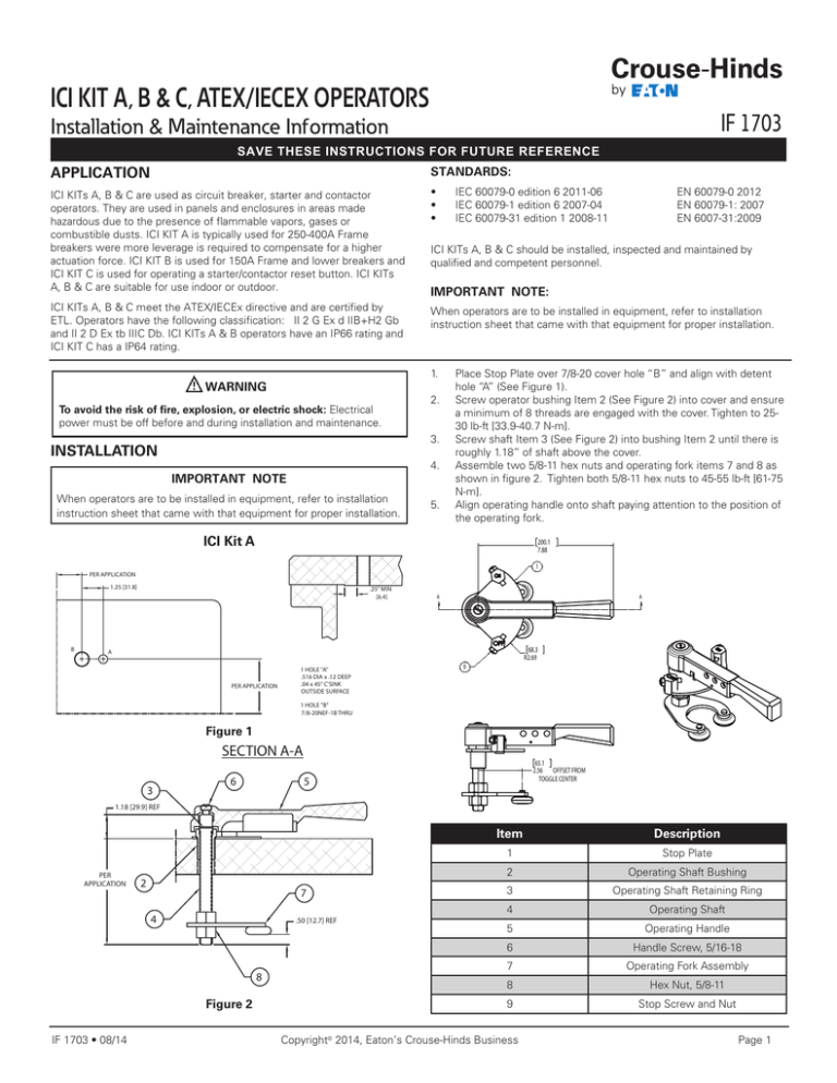
ICI KIT A, B & C, ATEX/IECEx OPERATORS IF 1703 Installation & Maintenance Information SAVE THESE INSTRUCTIONS FOR FUTURE REFERENCE APPlication STANDARDS: ICI KITs A, B & C are used as circuit breaker, starter and contactor operators. They are used in panels and enclosures in areas made hazardous due to the presence of flammable vapors, gases or combustible dusts. ICI KIT A is typically used for 250-400A Frame breakers were more leverage is required to compensate for a higher actuation force. ICI KIT B is used for 150A Frame and lower breakers and ICI KIT C is used for operating a starter/contactor reset button. ICI KITs A, B & C are suitable for use indoor or outdoor. • • • ICI KITs A, B & C meet the ATEX/IECEx directive and are certified by ETL. Operators have the following classification: II 2 G Ex d IIB+H2 Gb and II 2 D Ex tb IIIC Db. ICI KITs A & B operators have an IP66 rating and ICI KIT C has a IP64 rating. When operators are to be installed in equipment, refer to installation instruction sheet that came with that equipment for proper installation. To avoid the risk of fire, explosion, or electric shock: Electrical power must be off before and during installation and maintenance. IMPORTANT NOTE: 2. 3. INSTALLATION 4. IMPORTANT NOTE When operators are to be installed in equipment, refer to installation instruction sheet that came with that equipment for proper installation. EN 60079-0 2012 EN 60079-1: 2007 EN 6007-31:2009 ICI KITs A, B & C should be installed, inspected and maintained by qualified and competent personnel. 1. WARNING IEC 60079-0 edition 6 2011-06 IEC 60079-1 edition 6 2007-04 IEC 60079-31 edition 1 2008-11 5. Place Stop Plate over 7/8-20 cover hole “B” and align with detent hole “A” (See Figure 1). Screw operator bushing Item 2 (See Figure 2) into cover and ensure a minimum of 8 threads are engaged with the cover. Tighten to 2530 lb-ft [33.9-40.7 N-m]. Screw shaft Item 3 (See Figure 2) into bushing Item 2 until there is roughly 1.18” of shaft above the cover. Assemble two 5/8-11 hex nuts and operating fork items 7 and 8 as shown in figure 2. Tighten both 5/8-11 hex nuts to 45-55 lb-ft [61-75 N-m]. Align operating handle onto shaft paying attention to the position of the operating fork. ICI Kit A 200.1 7.88 1 PER APPLICATION 1.25 [31.8] B .25" MIN [6.4] A A 68.3 R2.69 A PER APPLICATION 1 HOLE "A" .516 DIA x .12 DEEP .04 x 45° C'SINK OUTSIDE SURFACE 9 1 HOLE "B" 7/8-20NEF-1B THRU Figure 1 SECTION A-A 3 6 65.1 2.56 OFFSET FROM TOGGLE CENTER 5 1.18 [29.9] REF PER APPLICATION 2 7 4 .50 [12.7] REF 8 Figure 2 IF 1703 • 08/14 Item Description 1 Stop Plate 2 Operating Shaft Bushing 3 Operating Shaft Retaining Ring 4 Operating Shaft 5 Operating Handle 6 Handle Screw, 5/16-18 7 Operating Fork Assembly 8 Hex Nut, 5/8-11 9 Stop Screw and Nut Copyright© 2014, Eaton’s Crouse-Hinds Business Page 1 IMPORTANT NOTE A 125.8 4.95 When operators are to be installed in equipment, refer to installation instruction sheet that came with that equipment for proper installation. 1 ICI Kit B PER APPLICATION .25" MIN [6.4] .75 [19.1] 41.3 R1.63 6 A A B 1 HOLE "A" 3/4-20NEF-2B THRU PER APPLICATION 1 HOLE "B" .437 DIA X .20±.05 DP OUTSIDE SURFACE 41.1 1.62 OFFSET FROM TOGGLE CENTER Figure 4 SECTION A-A Figure 6 Item 5 2 3 4 Description 1 Stop Plate 2 Operating Shaft Bushing 3 Operating Shaft 4 Operating Handle 5 Operating Fork Assembly 6 Stop Screw and Nut Operator Installation: 1.03 [26.1] REF .38 [9.5] REF PER APPLICATION 1. 2. Figure 5 3. 4. 5. IF 1703 • 08/14 Place Stop Plate over 3/4-20 cover hole “A” and align with detent hole “B” (See Figure 4). Screw operator bushing Item 4 (See Figure 5) into cover and ensure a minimum of 8 threads are engaged with the cover. Tighten to 2530 lb-ft [33.9-40.7 N-m]. Screw shaft Item 5 (See Figure 5) into bushing Item 4 until there is roughly 1.03” of shaft above the cover. Assemble operating fork as shown in figure 5. Tighten screw to 3545 lb-in [4.0-5.1 N-m]. Align operating handle onto shaft paying attention to the position of the operating fork. Copyright© 2014, Eaton’s Crouse-Hinds Business Page 2 IMPORTANT NOTE When operators are to be installed in equipment, refer to installation instruction sheet that came with that equipment for proper installation. Fork Adjustment: 1. 2. 3. 4. 5. 6. Measure distance from body flange to bottom of ICI Kit B and middle of ICI Kit A toggle (Dimension A). Measure distance from inside of cover to bottom of ICI Kit B and middle of ICI Kit A fork (Dimension B). Adjust fork up or down so that [B = A – 0.06”] for ICI KIT A and [B = A – 0.12”] for ICI KIT B. Move breaker toggle to “OFF” position and operator handle to “OFF” position. Close cover and check breaker operation. Adjust fork up or down to optimize breaker operation. Figure 7 Stop Adjustment: 1. 2. 3. 4. 5. 6. 7. 8. Move operator to “ON” position. Put light pressure on handle in the “ON” direction and hold in that position. Fork should be touching toggle. Turn stop screw until it touches handle. Tighten stop nut. Move operator to “OFF” position. Put normal pressure on handle in the “OFF” direction until the handle stops. Hold in that position. This represents the reset position. Turn stop screw until it touches handle. Tighten stop nut. Figure 8 IF 1703 • 08/14 Copyright© 2014, Eaton’s Crouse-Hinds Business Page 3 IMPORTANT NOTE Item Description When operators are to be installed in equipment, refer to installation instruction sheet that came with that equipment for proper installation. 1 Pushbutton Guard 2 Sleeve Locking Ring ICI KIT C 3 Push Button Shaft 4 Push Button Sleeve 1. 5 Hex Nut, 1/4-20 6 Reset Extension Button 2. 3. 4. Remove guards, indicating plates, outer locknuts, etc., to enable barrels to be threaded into the enclosure. Leave final locknut on barrel for mounting. Thread barrel assemblies into drilled and tapped holes 3 /4-14 NPSM from behind so they protrude to the enclosure front. Adjust length of barrel protrusion and thread inner locknut tightly against inside wall for mounting. Replace guards, indicating plates, outer locknuts, etc. WARNING To avoid explosion: clean both ground-joint surfaces of body and cover before closing. Dirt or foreign material must not accumulate on flat ground-joint surfaces. Surfaces must seat fully against each other to provide a proper explosionproof seal. 50.8 2.00 A maintenance A 1. Regular inspections should be made. A schedule for maintenance check should be determined by the environment and frequency of use. It is recommended that it should be at least once a year. 2. Perform visual, electrical, and mechanical checks on all components on a regular basis. 50.8 2.00 • Electrically check to make sure that all connections are clean and tight, and that contacts in the components make or break as required. • Mechanically check that all parts are properly assembled, and operating mechanisms move freely. 55.8 2.20 3. We recommend an Electrical Preventive Maintenance program as described in the National Fire Protection Association Bulletin NFPA No. 70B. REPLACEMENT PARTS ICI Kits are designed to provide years of reliable service. However, should the need for replacement parts arise, they are available through your Crouse-Hinds Distributor. Assistance may also be obtained through your Crouse-Hinds Sales Representative or the Crouse-Hinds Customer Service Department. Figure 9 SECTION A-A 1.54 [39.2] REF 1 compliances 2 • ATEX: • IECEx: ITS07ATEX15652U ETL14.0005U CONDITIONS OF USE • PER APPLICATION 3 4 5 .13 [3.2] REF 6 • • • • • Operators must be installed to provide a minimum 8 threads of engagement. These units have not been evaluated for ambient temperatures outside of -20°C to +60°C. The operators may be installed in enclosures where the reference pressure does not exceed 751.5 kPa (109 PSI) without further evaluation. ICI Kits must be installed per manufacturer’s instruction sheet IF1703. Machining of flamepaths is not allowed. Earthing of the components must be addressed in the end use. Figure 10 All statements, technical information and recommendations contained herein are based on information and tests we believe to be reliable. The accuracy or completeness thereof are not guaranteed. In accordance with Crouse-Hinds “Terms and Conditions of Sale,” and since conditions of use are outside our control, the purchaser should determine the suitability of the product for his intended use and assumes all risk and liability whatsoever in connection therewith. Eaton’s Crouse-Hinds Business 1201 Wolf Street Syracuse, New York 13208 • U.S.A. Copyright© 2014 IF 1703 R evision 1 New 08/14


