CL-7 Control Reference
Read equipment manufacturer’s manual and this material before using this product. Failure to
do so can result in death, severe personal injury, and equipment damage. G164.0
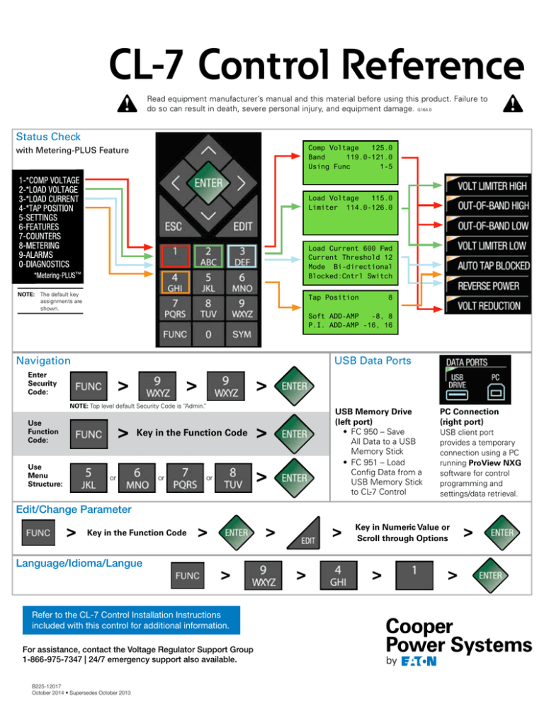
Status Check
Comp Voltage
125.0
Band
119.0-121.0
Using Func
1-5
with Metering-PLUS Feature
Load Voltage
115.0
Limiter 114.0-126.0
Load Current 600 Fwd
Current Threshold 12
Mode Bi-directional
Blocked:Cntrl Switch
NOTE: The default key
assignments are
shown.
Tap Position
8
Soft ADD-AMP
-8, 8
P.I. ADD-AMP -16, 16
USB Data Ports
Navigation
Enter
Security
Code:
NOTE: Top level default Security Code is “Admin.”
Use
Function
Code:
Use
Menu
Structure:
Key in the Function Code
or
or
or
USB Memory Drive
(left port)
• FC 950 – Save
All Data to a USB
Memory Stick
• FC 951 – Load
Config Data from a
USB Memory Stick
to CL-7 Control
PC Connection
(right port)
USB client port
provides a temporary
connection using a PC
running ProView NXG
software for control
programming and
settings/data retrieval.
Edit/Change Parameter
Key in the Function Code
Language/Idioma/Langue
Refer to the CL-7 Control Installation Instructions
included with this control for additional information.
For assistance, contact the Voltage Regulator Support Group
1-866-975-7347 | 24/7 emergency support also available.
B225-12017
October 2014 • Supersedes October 2013
Key in Numeric Value or
Scroll through Options
Main Menu
Sub-Menu
FC
Parameter
Factory Setting
Forward Direction..................................................................
001
002
003
004
005
051
052
053
054
055
040
140
049
041
042
043
044
044
045
045
045
046
144
145
146
141
050
Forward Set Voltage
Forward Bandwidth
Forward Time Delay
Forward Line Drop Compensation R
Forward Line Drop Compensation X
Reverse Set Voltage
Reverse Bandwidth
Reverse Time Delay
Reverse Line Drop Compensation R
Reverse Line Drop Compensation X
Regulator Identification
Regulator Type
Tap-Changer Type*
Regulator Configuration
Control Operating Mode
System Line Voltage
Overall P.T. Ratio
Internal P.T. Ratio
C.T. Primary Rating
Rated Load Current
% C.T. Rating Level (4-1)
Demand Time Interval
P.I. ADD-AMP High Limit
P.I. ADD-AMP Low Limit
Vin P.T. Configuration
Regulator Identification
System Calendar and Clock
120.0
2.0
45
0.0
0.0
120.0
2.0
45
0.0
0.0
panel serial number
per nameplate
per nameplate
per nameplate
Sequential
per nameplate
per nameplate
per nameplate
per nameplate
per nameplate
per nameplate
15.0
16
-16
Vdiff Mode
----------
069
056
039
080
070
Auto Operation Blocking Status*
Reverse Sensing Mode
Source-Side Calculation
Voltage Limiter Mode
Voltage Reduction Mode
Normal
Locked Forward
On
Off
Off
Settings
Reverse Direction..................................................................
Configuration.........................................................................
Calendar/Clock......................................................................
Multi-Phase Config
Features
Auto-Block Status..................................................................
Reverse Power Mode............................................................
Source-Side Voltage Calc.......................................................
Voltage Limiter.......................................................................
Voltage Reduction..................................................................
Tap-to-Neutral
Soft-ADD-AMP™ Feature
Alternate Config
Leader Follower
Calibration
Battery
Operations Counter
Counters
Metering
Instantaneous
Forward Demand
Reverse Demand
Master Reset
* For quick troubleshooting, check
FC 49 Tap Changer Type and
FC 69 Auto Block Status.
NOTE: The default key
assignments are
shown.
Alarms Active Unacknowledged
Alarms Active Acknowledged
Alarms
Sequence of
Events
Communications
Diagnostics
Test LEDs
Control
Communications
Maintenance
Sync Counters
Metering-PLUS Feature
Menu System
USB Memory
Drive
Turn Off Display
Cooper
Power
Systems
Eaton’s
Cooper
Power
Systems
Badger
23002300
Badger
DriveDrive
Waukesha,
WI
53188
Waukesha, WI 53188
P: 877.CPS.INFO
P: 877.CPS.INFO
www.cooperpowersystems.com
Eaton, Cooper Power Systems, Metering-PLUS, and ProView NXG are valuable trademarks of Eaton in the U.S. and other countries.
You are not permitted to use these trademarks without the prior written consent of Eaton.
©2014 Eaton. All Rights Reserved


