Finding Redundant Constraints in FSM Minimization
Lin Yuan, Pushkin R. Pari and Gang Qu
Department of Electrical and Computer Engineering
University of Maryland, College Park, Maryland, 20742
{yuanl,pushkin,gangqu}@eng.umd.edu
Introduction
Finite state machine (FSM) is a computation model that consists of a finite set of states, a start state, an input alphabet,
and a transition function that defines the next state and/or
outputs based on the current state and input symbols.
Finding an equivalent FSM with minimal number of states
is generally referred as state minimization or state reduction
(SR) problem. State minimization is an effective approach in
logic synthesis to optimize sequential circuit design in terms
of area and power(Kam, 1997). The SR problem of FSM
is NP-complete and can be treated as a special case of the
Constraint Satisfaction Problem(CSP) where the transition
function defines all the constraints that need to be satisfied.
Interestingly, we observe that not all the constraints are required to obtain a given SR solution. Identifying the redundancy in the FSM will be useful in the following occasions.
First, it helps to understand the nature of the NP-complete
SR problem and to build FSM benchmarks to test the effectiveness of SR solvers. Second, the redundancy can be utilized to hide information and thus provide security protection to the FSM. Simulation results on real life FSMs reveal
the existence of extremely rich redundancy.
Motivational Example
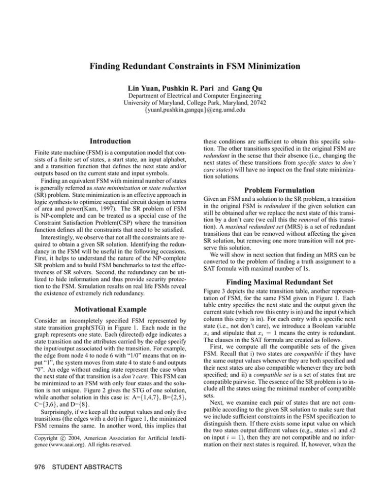
Consider an incompletely specified FSM represented by
state transition graph(STG) in Figure 1. Each node in the
graph represents one state. Each (directed) edge indicates a
state transition and the attributes carried by the edge specify
the input/output associated with the transition. For example,
the edge from node 4 to node 6 with “1/0” means that on input “1”, the system moves from state 4 to state 6 and outputs
“0”. An edge without ending state represent the case when
the next state of that transition is a don’t care. This FSM can
be minimized to an FSM with only four states and the solution is not unique. Figure 2 gives the STG of one solution,
while another solution in this case is: A={1,4,7}, B={2,5},
C={3,6}, and D={8}.
Surprisingly, if we keep all the output values and only five
transitions (the edges with a dot) in Figure 1, the minimized
FSM remains the same. In another word, this implies that
c 2004, American Association for Artificial IntelliCopyright gence (www.aaai.org). All rights reserved.
976
STUDENT ABSTRACTS
these conditions are sufficient to obtain this specific solution. The other transitions specified in the original FSM are
redundant in the sense that their absence (i.e., changing the
next states of these transitions from specific states to don’t
care states) will have no impact on the final state minimization solutions.
Problem Formulation
Given an FSM and a solution to the SR problem, a transition
in the original FSM is redundant if the given solution can
still be obtained after we replace the next state of this transition by a don’t care (we call this the removal of this transition). A maximal redundant set (MRS) is a set of redundant
transitions that can be removed without affecting the given
SR solution, but removing one more transition will not preserve this solution.
We will show in next section that finding an MRS can be
converted to the problem of finding a truth assignment to a
SAT formula with maximal number of 1s.
Finding Maximal Redundant Set
Figure 3 depicts the state transition table, another representation of FSM, for the same FSM given in Figure 1. Each
table entry specifies the next state and the output given the
current state (which row this entry is in) and the input (which
column this entry is in). For each entry with a specific next
state (i.e., not don’t care), we introduce a Boolean variable
xi and stipulate that xi = 1 means the entry is redundant.
The clauses in the SAT formula are created as follows.
First, we compute all the compatible sets of the given
FSM. Recall that i) two states are compatible if they have
the same output values whenever they are both specified and
their next states are also compatible whenever they are both
specified; and ii) a compatible set is a set of states that are
compatible pairwise. The essence of the SR problem is to include all the states using the minimal number of compatible
sets.
Next, we examine each pair of states that are not compatible according to the given SR solution to make sure that
we include sufficient constraints in the FSM specification to
distinguish them. If there exists some input value on which
the two states output different values (e.g., states s1 and s2
on input i = 1), then they are not compatible and no information on their next states is required. If, however, when the
0/1
0/1
0/1
8
1
1/1
1
2
1/0
0/−
0/1
2
8
1/1
0/1
1/1
1/1
1/0
1/0
4
6
4
5
1/0
6
1/0
5
0/0
0/0
1/0
0/0
1/1
1/−
7
0/1
1/−
7
3
In=0
In=1
1 (x1 )
6 (x2 )
8 (x3 )
5 (x4 )
1 (x5 )
6 (x6 )
3 (x7 )
8 (x8 )
5 (x9 )
6 (x10 )
8 (x11 ) 6 (x12 )
Next State
1
2
3
4
5
6
7
8
3
In=0 In=1
1
0
1
0
1
0
0
1
0
0
1
1
1
Output
0/0
Figure 1: STG for the FSM.
Figure 2: STG for the reduced FSM.
two states, for every input value, either have the same output value or at least one has a don’t care as its output, then
we need the information on their next states to distinguish
them. Take states s2 and s3 for instance, the only way to
distinguish them is to make both transitions x3 and x4 nonredundant, which can be done by including the expression
x′3 x′4 into the SAT formula.
A more complicated example is the pair of states s2 and
s8. Their respective next states s6 and s8 are not compatible
and we need the presence of both transitions x2 and x11 or
x3 and x12 to distinguish them. This can be conveniently enforced by the following Boolean expression (in CNF format)
x′2 x′11 + x′3 x′12
(DeM organ) ⇒ (x2 + x11 )(x3 + x12 )
(Distributive) ⇒ x2 x3 + x2 x12 + x11 x3 + x11 x12
′
′
′
′
′
′
′
′
(DeM organ) ⇒ (x2 + x3 )(x2 + x12 )(x11 + x3 )(x11 + x12 )
As a result, for the FSM in Figure 1 and its SR solution in
Figure 2, we have the following SAT instance:
F = x′3 x′4 x′10 (x′2 + x′3 )(x′3 + x′11 )(x′2 + x′12 )(x′11 + x′12 )x′8
For variables that do not appear in this formula (such as x1 ),
we can safely assume that their corresponding transitions are
redundant. Clearly, finding the MRS becomes equivalent to
finding a solution to the corresponding SAT formula such
that the number of variables assigned to be ‘1’ is maximized.
An exact algorithm is to formulate it as an integer linear programming(ILP) problem which has been discussed in (Aloul
et al. 2002). Practically, one can also simply solve the SAT
formula multiple times, each solution represents one MRS,
and pick the one with the maximal 1s.
Results and Discussion
We consider FSM benchmarks from the MCNC suite of
sequential circuits (Yang 2002). For each FSM, we use
stamina from the logic synthesis package SIS (Sentovich &
others 1992) to obtain a solution to the SR problem. We then
generate the SAT instance and solve it by a SAT solver zchaff
(Moskewicz et al. 2001) and ILP solver CPLEX(ILO 2002).
We report the redundancy of each FSM benchmark in Table
1. The 2nd and the 3rd columns give the number of states
and transitions in the original FSM; the next two columns
report the number of redundant constraints identified by ILP
solver and the percentage in the original constraints; the last
Figure 3: State table for the FSM.
Table 1: Redundant constraints in FSM benchmarks
FSM
states
donfile
ex2
ex3
ex5
ex7
example
lion9
modulo12
s27
s8
train11
opus
beecount
bbara
mark1
24
19
10
9
10
6
9
12
6
5
11
10
7
10
15
orig.
constr.
96
72
36
32
36
24
25
12
96
80
25
176
51
160
240
cplex
redun
ratio
96
100%
27
38%
19
53%
19
59%
20
56%
24
100%
12
48%
12
100%
88
92%
80
100%
5
20%
176
100%
36
71%
36
23%
129
54%
zchaff
redun
ratio
96
100%
15
21%
10
28%
9
28%
14
39%
24
100%
12
48%
12
100%
85
89%
80
100%
3
12%
176
100%
34
67%
33
21%
128
53%
two columns show the similar result obtained by the SAT
solver. One can see that both the ILP and SAT solvers manage to find very rich redundancy (from 12% to 100% with
an average of 66%). Most of the 100% redundancy occurs
when the original FSM is minimized to a single state FSM.
In sum, we introduce the concept of redundancy in FSM
specification and formulate the problem as finding a SAT solution with maximal number of 1s. We expect to find some
more real-world applications where this redudant information can be utilized.
References
Aloul, F.; Ramani, A.; Markov, I. L.; and Sakallah, K. A.
2002. Generic ilp versus 0-1 specialized ilp. In IEEE/ACM
International Conference on Computer Aided Design, 450–
457.
ILOG Inc. 2002. ILOG AMPL CPLEX System Version 8.0
Use Guide.
Moskewicz, M. W.; Madigan, C. F.; Zhao, Y.; Zhang, L.;
and Malik, S. 2001. Chaff: Engineering an efficient sat
solver. In The 38th ACM/IEEE Design Automation Conference, 530–535.
Sentovich, E. M., et al. 1992. Sis: A system for sequential
circuit synthesis. Technical report, Electronics Research
Laboratory, University of California, Berkeley.
Yang, S. 2002. Synthesis and optimization benchmarks
user guide. Technical report, ftp://mcnc.mcnc.org.
STUDENT ABSTRACTS 977

