From: AAAI-97 Proceedings. Copyright © 1997, AAAI (www.aaai.org). All rights reserved.
Qualitative
,Thomas
Rigid
MIT AI Lab
Cambridge, MA 02139
davis@ai.mit.edu
Abstract
We present a theory of qualitative
rigid body mechanics and describe a program that uses this theory to compute qualitative
dynamic simulations.
The program
works directly from a qualitative
representation
of geometry
(qc-space).
It employs a new qualitative
representation
for forces
that reduces ambiguity
in force sums and hence
reduces branching.
Introduction
Our work is motivated by the task of interpreting rough
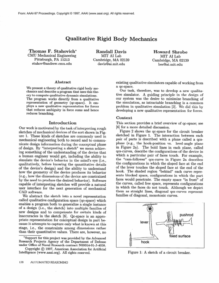
sketches of mechanical devices of the sort shown in Figure 1. These kinds of sketches are commonly used in
mechanical engineering both to record and to communicate design information during the conceptual phase
of design. By “interpreting a sketch” we mean achieving something of the understanding of the device that
a human engineer would get, including the ability to
simulate the device’s behavior in the mind’s eye (i.e.,
qualitatively, before knowing the quantitative details
of the device’s design) and the ability to understand
how the geometry of the device produces its behavior
(e.g., how the dimensions of the device are constrained
by the need to produce the desired behavior). Software
capable of interpreting sketches will provide a natural
user interface for the next generation of mechanical
CAD software.
We abstract the sketch into a novel representation
called qualitative configuration space (qc-space) which
enables a program both to generalize a single instance
of a design (i.e., the sketch) into multiple families of
new designs and to compensate for certain kinds of
inaccuracies in the sketch [6]. Qc-space is an appropriate representation for conceptual design in part because it attempts to capture only what is known at this
stage, i.e., the constraints among dimensions rather
than their quantitative values. There are, however, no
*Support for this project was provided by the Advanced
Research Projects Agency of the Department
of Defense
under Office of Naval Research contract N00014-91-J-4038.
Copyright
@ 1997, American Association for Artificial
Intelligence
(www.aaai.org).
All rights reserved.
AUTOMATED
Mechanics
F. Stahovich*
CMU Mechanical Engineering
Pittsburgh, PA 15213
stahov@andrew.cmu.edu
138
Body
REASONING
oward
Shrobe
MIT AI Lab
Cambridge, MA 02139
hes@ai.mit .edu
existing qualitative simulators capable of working from
a qc-space.
Our task, therefore, was to develop a new qualitative simulator.
A guiding principle in the design of
our system was the desire to minimize branching of
the simulation, as intractable branching is a common
problem in qualitative simulation [3]. We did this by
developing a new qualitative representation for forces.
Context
This section provides a brief overview of qc-space; see
[6] for a more detailed discussion.
Figure 2 shows the qc-space for the circuit breaker
sketched in Figure 1. The interaction between each
pair of parts is described with a plane called a qcsplane (e.g., the hook-position vs. level-angle plane
in Figure 2a). The bold lines in each plane, called
qcs-curves, describe the configurations of the device in
which a particular pair of faces touch. For example,
the “cam-follower” qcs-curve in Figure 2a describes
the configurations in which the sloped face at the end
of the lever touches the sloped face at the end of the
hook. The shaded region “behind” each curve represents blocked space, configurations in which the part
faces would penetrate. The empty space “in front” of
the curves, called free space, represents configurations
in which the faces do not touch. Although we depict
them as straight lines, diagonal qcs-curves represent
families of diagonal, monotonic curves.
Figure 1: A sketch of a circuit breaker.
Hook
Pushrod
Position
j hook=cold
--------:-----------mi
c: :
‘C
a:
3:
gi
ui
j:..hook=hot
____-_
__-______
lb
Levbr Angie
’ (b)
Lever
Angie
Figure 2: The qc-space for the circuit breaker. The
hook-pushrod qcs-plane is not shown because there are
no interactions between the hook and pushrod. “leverstop” = interaction between back of hook and front
of lever. “cam-follower” = interaction between sloped
faces on hook and lever. “push-pair” = interaction
between end of pushrod and side of lever. “pushrodstop” = interaction between pushrod and fixed surface.
In general, the dimension of a qc-space is equal to the
number of degrees of freedom in the device. Because we
restrict our attention to devices with fixed-axis parts
(each part rotates about a fixed axis or translates along
a fixed axis), we can represent a multi-dimensional
qcspace as a set of 2D projections, i.e., the qcs-planes.
In addition to interacting faces, our devices may also
contain springs and actuators (motion sources). We assume that springs have one end fixed and the other end
attached to a moving body; hence, the locus of configurations in which a spring is relaxed can be represented
as a horizontal or vertical boundary in the qcs-plane.
For example, the “lever-spring” boundary (dashed line
in Figure 2b) represents the neutral position of the
spring attached to the lever.
An actuator is an external motion applied to a degree of freedom, e.g., in the circuit breaker an actuator
represents the user’s push on the reset pushrod. We
assume that actuators apply finite motions. Similar to
the neutral position of a spring, we represent the extent of an actuator’s motion with either a horizontal
or vertical boundary. The boundary labeled “motion
limit” (Figure 2b), for example, represents the extent
to which the user can push the reset pushrod.
We mark with landmarks the end points of finite
qcs-curves and the axis crossing of horizontal boundaries, vertical boundaries, and infinite qcs-curves (such
as the “pushrod-stop”).
The ordering of the landmarks
encodes the relative locations of the curves and boundaries; there are no absolute locations in qc-space.
Our simulator computes the motion a device’s parts
directly from the device’s qc-space. The simulator describes the motions as a sequence of configurations that
we call a trajectory through the qc-space. For example,
the trajectory indicated by the bent arrow in Figure 2a
describes the motions of the lever and hook that occur
when the circuit breaker trips. (The hook is a bimetallic strip; during overload the hook heats and bends.)
As the trajectory moves down the lever-stop curve the
hook is disengaging the lever. Once they disengage,
the hook continues to move toward its hot neutral position (“hook=hot”
boundary) while the lever is pushed
to the right by the lever-spring.2
The trajectory in Figure 2b provides another view
of the tripping action of the circuit breaker, this time
describing the motions of the lever and pushrod: The
pushrod remains against its stop, thus the trajectory
follows the pushrod-stop qcs-curve while the lever is
pushed to the right by its spring. Eventually the trajectory terminates by colliding with the push-pair qcscurve, corresponding to the lever coming to rest against
the end of the pushrod.
epresenting
Forces
As we know from Newton’s laws of motion, to compute
the motion of a body one must first compute the net
force on it. Unfortunately
in a qualitative world this
can be a difficult task. Consider, for example, the three
blocks in Figure 3. The spring pushes block A to the
right, the actuator pushes block C to the left. Block
B, the block in the middle, experiences two forces, one
from A and one from C. Because the forces are in opposite directions, their qualitative sum is ambiguous.
Figure 3: Three blocks on a frictionless surface.
However, we know that B will move to the left.
Why? We know that the force C applies to B is whatever force is necessary for C to achieve its assigned
motion (the actuator imparts a known motion to C).
Apparently, a qualitative force representation that captures only the direction of a force is inadequate to support this kind of conclusion. In response we developed
a force representation with four properties: direction,
magnitude,
type, and interface
motion,
and use it to
substantially reduce ambiguity.
We discuss each of
these in turn, but begin by considering another ambiguity reducing insight.
Simplifying
Forces
Forces in 3-space are commonly described by their vector components, i.e., their projections on each of the
coordinate axes. But the only components of a force
that have any effect on the motion of a body are the
projections of the force onto the body’s degrees of freedom. Because we consider only fixed-axis bodies, i.e.,
2We
neutral
model
position
the bimetallic
strip
as a spring
having
one
when
it is cold, and another
when
it is hot.
REASONING
ABOUT
PHYSICAL
SYSTEMS
139
those with only one degree of freedom, we need consider only one projection. 3 This results in a substantial
reduction in potential ambiguity compared to previous
qualitative force representations (e.g., [2]) which consider all three vector components.
Direction
and
Magnitude
Having focused in on the single projection of the force
that matters, we describe direction with one of the
three standard (qualitative) values +, -, or 0. The
direction is + if the force has a component in the direction of positive motion, - if the force has a component
in the direction of negative motion, and 0 if the force is
perpendicular to the direction of motion. We describe
magnitude as 0 if the force has zero magnitude and I
otherwise.
Force
Type
The qualitative property we call “force type” was inspired by the situation depicted in Figure 3 in which
C applies what we call a “motion constrained engagement force,” a force that constrains the motion of the
body to which it is applied.
According to Hooke’s law, the spring’s deflection determines the magnitude of the spring’s force on A. If
inertia is negligible, A will transmit the spring force to
B.4 Thus, A applies a force of known magnitude to B.
In contrast to a motion constrained engagement force
which assigns a known motion, this kind of force assigns a known magnitude. We call this type of force a
“compliant engagement force” because it has a known
magnitude in the same way that a compliant member
(e.g., a spring) produces a force of known magnitude.
This distinction enables one of our basic principles:
a motion constrained engagement force overpowers a
compliant engagement force. Because there is a motion constrained engagement pushing B to the left and
a compliant engagement pushing B to the right, B must
move to the left in Figure 3. In our experience, this
principle has proven very useful in resolving ambiguities in force sums.
Interface
Motion
The fourth component of our qualitative representation of forces is interface motion. To see what we mean
by this, consider that in the example of Figure 3 we decided that block B will move to the left because there
is a motion constrained engagement force pushing it
in that direction. Now imagine that the actuator attached to block C pushes C to the right instead of the
left. Because C will still apply a position constraint to
3This
works
equally
well if the body
rotates
instead
of
translates.
In this
case we compute
the moment
of the
force
about
a point
on the axis of rotation,
then
project
this moment
onto the axis.
4We assume
motion
is inertia-free
for reasons
described
below.
140
AUTOMATED
REASONING
B, the force C applies to B will still be a motion constrained force whose direction is still toward the left.
But in this case block B will move to the right.
A convenient way to describe the difference between
these two situations is in terms of the relationship between the direction of C’s motion and the direction of
the force it applies to B. With the actuator moving to
the left, they are in the same direction. In this case we
say that C is applying an “advancing force.” With the
actuator moving to the right, C’s motion and the force
C applies to B are in opposite directions, and we say
that C is applying a “retreating force.” (If the actuator
holds C fixed, we say that C is applying a “stationary
force.“)
We now have four properties with which to describe
an engagement force: the direction of the force-[+,
or I], its type-[motion
-9 or 01, its magnitude-[0
constrained or compliant], and the interface motion[advancing, retreating, or stationary].
We stated previously that a motion constrained engagement force always overpowers a compliant one. By
considering the interface motion of a force we can state
this principle more precisely: An advancing motion
constrained force causes movement in the direction of
the force; a stationary motion constrained force prevents movement opposite the force; and a retreating
motion constrained force allows movement opposite the
force, not faster than the speed of retreat. In our experience, this more precise version of the principle is
quite effective in resolving ambiguities in force sums.
Computing
Motion
Because we use a qualitative representation, and because bodies are fixed-axis, we describe the motion
(velocity) of a body with the standard values of +,
-, and 0. Because we assume motion is inertia-free,
the motion is always in the direction of the net force.5
To compute the net, force the program must first
compute the values of the four qualitative properties
of each force. Our program begins by determining the
qualitative direction and type of each force.
The qualitative direction of a force can easily be
obtained by direct examination of the qc-space: the
direction is given by the outward normal to the qcscurve. The other three properties are determined by
constraint propagation techniques.
The program uses constraint propagation to systematically identify all of the motion constrained forces,
then labels the remaining forces as compliant because
there is no other choice.
The program begins by identifying all of the obvious
motion
constrained
forces:
The engagement
forces
produced by stationary bodies and the engagement forces
produced by bodies positioned by actuators are motion
constrained.
Then the program uses a constraint
net
5With
force
inertia,
but the
the acceleration
velocity
need
not
is in the
be.
direction
of the
spring,
engagement force
external motion constrained 1 compliant
I
01
o
1 I
lOlolol
I
I
I
I
I
I
I
1 0
1
I
I I
I
I
0
motion
0
0
1 BI
101 o lolololololol
BI
Figure 4: A translates horizontally, B vertically. Fixed
surface S engages A. F is the qualitative force of A on B
(i.e., the projection of the actual force onto the degree
of freedom); M is the qualitative force of B on A.
I
propagation technique to identify all of the motion constrained forces that result from these.
The propagation technique is based on the following rule: Body-l applies a motion constrained force
to body-2 if and only if the force that body-2 applies
to body-l is resisted by some other motion constrained
force applied to body-l. For example, in Figure 4 force
F is motion constrained because force M is resisted by
force P, a motion constrained force applied by the fixed
surface.
The simulator applies this rule repeatedly until no
new motion constrained forces are identified. If all of
the obvious cases are identified first, this propagation
technique is guaranteed to identify all of the motion
constrained forces.
To illustrate this procedure, we apply it to the blocks
in Figure 3. We begin by labeling the obvious case:
C applies a motion constrained force to B because C
is positioned by an actuator.
Using the propagation
rule, we determine that B applies a motion constrained
force to A. The rule cannot be applied to any other
engagements, thus the remaining forces are compliant.
Having determined the direction and type of the
forces, we turn next to magnitude and interface motion. We need to solve for these two properties and
the motion all at the same time. To see why, note
that if two bodies are touching but the instantaneous
motions are causing the bodies to separate, the magnitudes of the engagement forces will be 0. However, if
the instantaneous motions cause the bodies to remain
in contact, the magnitudes may be non-zero. Similarly,
to compute the motion of a set of bodies one must first
know the interface motion of each of the forces, but to
determine the interface motion of the forces one must
first know the motion of each of the bodies.
Here we use another version of constraint propagation to simultaneously solve for the magnitude and
interface motion of the forces and the motion of the
bodies. Our approach, variously referred to as “opportunistic search” or “constraint propagation with assumed states and backtracking” [7] ) propagates motion
from one body to the next. Our program starts the
propagation process by determining the motion of each
0
0
1
lalol
0
0
0 0
Cl
0
I
I
I
I
0
0
0
0
0
0
0
0
0
0
0
0 0
)
0 0
0
0
0
Table 1: A body’s motion is consistent with the applied forces if the motion and the forces match one of
these rules. Any combination not listed is inconsistent.
q = one or more. o= zero or more. blank = none. A
= advancing, S = stationary, R = retreating.
“BY
(bad input) indicates that the user specified incompatible inputs: an actuator pushing against a stop or two
actuators pushing against each other. The magnitude
of spring forces and external forces must be 1. The
magnitude of engagement forces is unspecified.
body positioned by an actuator, which is simply the
motion of the actuator. The simulator then attempts
to propagate motion from the bodies with known motion to those they touch, repeating the propagation
until it subsides.
Propagation can stall before we have computed the
motion of all of the bodies. To prevent this, we use a
heuristic to guess values for motion: if all of the forces
have the same direction, we guess the motion will be in
this direction. (This assumption will be wrong if none
of the forces have advancing interface motion and nonzero magnitude.) After we have computed or guessed
a value for the motion of each body, the program uses
Table 1 to check whether all the motions are consistent
with the forces.6 If not, the program chooses different
motions for the bodies whose motion was inconsistent
with the applied forces.
Our heuristic can even be applied to some situations
in which the forces do not all have the same direction.
The additional insight is that any forces whose interface motion is known to be retreating can safely be
ignored, because they have no effect on the motion of
a body. If, when retreating forces are ignored the re‘For
a motion
C) and
A), the
example,
because
block
B in Figure
constrained,
-, advancing
engagement
a compliant,
+, retreating
engagement
eighth
row of the table
tells us that
REASONING
ABOUT
PHYSICAL
3 experiences
force (from
force
(from
B’s motion
is
SYSTEMS
141
maining forces all have the same direction, then the
original heuristic applies.
While this augmented heuristic was sufficient to prevent blocking in all of our examples, there are likely to
be situations in which the heuristic will be insufficient.
In those cases we would have to randomly choose the
motion for one body each time the propagation blocks,
then, if necessary, backtrack as before.
The Next
Event
Our simulator is event-oriented: each time step continues until there is a change in the nature of the forces,
which in turn causes a change in the motion of the
bodies. Four kinds of events can cause such a change:
an engagement is broken (a pair of faces separate), an
engagement is made (two faces collide), a spring passes
through its neutral position, or an actuator reaches its
limit of motion. The first kind of event occurs when a
trajectory following a qcs-curve reaches the end of that
curve, s7 the other kinds of events occur when the trajectory hits a new qcs-curve.’ Hence, to determine the
next event, we must examine the trajectory through
qc-space.
We make a number of assumptions about devices
that greatly simplify the task of reasoning about trajectories. We assume that qcs-curves are monotonic,
that motion is inertia-free, and that collisions are inelastic. As a result, until the forces on a body change,
the motion of the body remains either strictly positive,
strictly negative, or zero. Consequently, all trajectories
in qc-space are monotonic over any given time step.
We assume also that devices are fixed-axis and as
a result we can examine the trajectory through a
multi-dimensional
qc-space by examining the trajectories through 2D projections of the space, i.e., the
qcs-planes. We compute the next event, and hence the
next state of the device, by first determining which
events would happen if the trajectory in each qcs-plane
continued until an event occurs in that plane, then using constraint propagation to determine which of the
events predicted by the individual planes can happen
first.
Events
in the
Plane
If the trajectory follows a qcs-curve, the next event occurs when the trajectory reaches the end of that curve
or when the trajectory reaches the intersection of that
curve and another curve. For example, if the pushrod
is against its stop and the lever is moving to the right
71f the trajectory
leaves
perpendicular
to the qcs-curve
rather
than reaching
the end of the curve,
there
is no change
in the forces.
In this
case,
the engagement
forces
were
retreating
and hence
had a zero magnitude
even before
the
pair of faces separated.
8For the sake of brevity,
we use the term
“qcs-curve”
to
refer
to both
qcs-curves
and the boundaries
that represent
spring
neutral
positions
and the motion
limits
of actuators.
142
AUTOMATED
REASONING
(Figure 5), the trajectory in the lever-pushrod qcsplane will follow the pushrod-stop curve (Figure 6).
The next event in that plane occurs when the trajectory reaches the intersection of the pushrod-stop and
push-pair curves, i.e., when the lever hits the end of
the pushrod.g
I
I
Figure 5: Lever-spring pushes lever counterclockwise
and hook moves towards its cold neutral position.
Hook is high enough that lever cannot miss it.
Pushrod
Position
I ll, k
Ii
Lever Angler
Figure 6: Next event occurs when trajectory (thick
arrow) hits push-pair. La is start point of trajectory.
If the trajectory in a qcs-plane is horizontal or vertical (and does not follow a qcs-curve), the simulator
determines the next event by looking along the direction of motion to see which qcs-curve is reached first. If
the trajectory does not intersect any qcs-curves, then
no event will occur in this plane (and thus the motion
will continue without bound).
If the trajectory is diagonal (and does not follow
a qcs-curve), the simulator must perform more complicated geometric reasoning to determine what event
happens next. The simulator uses a process of elimination to identify which qcs-curves can be reached:
it determines geometrically all of the qcs-curves that
cannot be reached; any remaining qcs-curves can be
reached.
Consider, for example, the diagonal trajectory in
Figure 7 which corresponds to motion of the lever and
hook shown in Figure 5. The simulator begins by
defining a new coordinate system with its origin at the
‘As
Figure
we
7.
will
see,
this
event
is prevented
by
an event
in
hook=hot
Figure 7: Trajectory in qc-space (thick arrow) is diagonal. The active region of the qcs-plane is shaded.
starting point of the trajectory. Because the trajectory
is monotonic, it will remain entirely in one quadrant
of the new coordinate system; we call this the active
quadrant. Any qcs-curve that lies completely outside
the active quadrant cannot be reached by the trajectory.
Now imagine a “chain” of qcs-curves that divides
the active quadrant into two regions, only one of which
includes the origin. We call the region that includes the
origin the active region. Figure 7 shows an example in
which the chain is composed of the lever-stop and the
“hook=cold” qcs-curves; the active region is shown as
a shaded rectangle. The trajectory cannot reach any
qcs-curve that lies completely outside the active region.
There may be more than one chain that separates
the active quadrant into two regions. For example,
in Figure 7, there are three chains: the lever-stop and
“hook=cold” chain, the cam-follower and “hook--cold”
chain, and the lever-spring and “hook=cold”
chain.
When there are multiple chains, any qcs-curve that
lies completely outside the smallest chain cannot be
reached. lo
The trajectory can reach any qcs-curve inside the
smallest chain and can reach all of the curves that compose the chain. In the example of Figure 7 for instance,
only the “hook=cold” and the lever-stop curves can be
reached. In this case, there are three possible events:
The trajectory can reach the lever-stop curve, in which
case the lever strikes the hook; the hook can reach the
“hook=cold”
curve, in which case the hook relaxes;
and the trajectory can reach the intersection of these
two curves, in which case the lever strikes the hook at
the same instant the hook relaxes.
The
Next
State
To compute the possible next states of the device, the
simulator picks one event , possibly a null event (i.e.,, no
“The
smallest
chain
is determined
mark
values:
in this case its the one
imum
x-coordinate.
by
with
comparing
the smallest
landmax-
event occurs and there is no changes in the forces), for
each qcs-plane. It then checks if this set of events (one
from each plane) places consistent constraints on the
positions of the bodies. If the constraints are consistent (i.e., the bodies can all be in the required locations
at the same time), this set of events can happen simultaneously and hence represents a possible next state
of the device. The simulator repeats this process for
each possible combination of events obtained by choosing one event for each plane. l1 If there is more than
one consistent set of events, i.e. more than one possible
next state, the simulator generates them all, producing
an envisionment .
We illustrate this process by showing how the program determines the next states from the events predicted in Figure 6 and Figure 7.12
The first step is to express the position constraints
imposed by an event as simple equalities and inequalities between landmarks.
For example, for the next
event in Figure 6 to occur the position L of the lever
must satisfy the constraint: L = B. Likewise, the null
event is described by: LO < L < B.
In the same fashion the program describes the three
possible events in Figure 7 with the constraints: [L =
A, HO < H < C], [LO < L < A, H = C], and [L = A,
H = C], where H is the position of the hook.
When the trajectory is diagonal, as it is in Figure 7,
we use a tiling procedure to construct the constraints
for the null event. The simulator first computes the
smallest chain as described above, then tiles the active region of this chain with rectangular tiles as the
example in Figure 8 illustrates.13 The null event corresponds to the trajectory terminating in any tile that
does not contain a qcs-curve (these tiles are shaded in
the figure). In Figure 7 there is only one tile and the
null event is given by: [La < L < A, HO < H < C] .
With all of the events from the individual planes expressed as constraints, the simulator is ready to enumerate possible next states of the device (i.e., sets of
globally consistent next events). Because there are two
possible events in Figure 6 (including the null event)
and four in Figure 7 (also including the null event),
the simulator must consider a total of seven sets of
next events (eliminating the set consisting entirely of
null events). One set of events, for example, consists
of the lever hitting the pushrod in Figure 6 (L = B)
and the lever hitting the hook in Figure 7 ([L = A,
Ho < H < Cl). Th is set of events places inconsistent constraints on the position of the lever (A # B)
and hence is not a possible next state. A second set
llThe
simulator
does,
however,
throw
out the combination that
consists
only of null events,
because
that
combination
corresponds
to the current
state.
12Because
the circuit
breaker
has 3 degrees
of freedom,
there are 3 qcs-planes.
However,
in this case the third
plane
provides
no additional
information
about
the next event.
13The
program
places
artificial
boundaries
at + and infinity
to ensure
there
is always
a chain.
REASONING
ABOUT
PHYSICAL
SYSTEMS
143
Figure 8: Tiling the active region. There is a column
of tiles for each landmark along the abscissa, and a row
for each landmark along the ordinate. The shaded tiles
constitute the null event.
of events has the null event occurring in the Figure 6
(Lo < L < B) and the lever still hitting the hook
in Figure 7. Because these constraints are consistent,
this set of events is a possible next state of the device.
Continuing in this fashion we find that there are a total
of three possible next states: each of the three events
from the Figure 7 (hook relaxing, lever hitting hook,
and hook relaxing just as lever hits hook) combined
with the null event in Figure 6.
The program extends the simulation from each of
these three states to produce an envisionment of the
circuit breaker’s behavior. As this example illustrates,
our simulator can compute an envisionment of a device
solely from the information contained in the qc-space,
i.e. the qualitative slopes and relative locations of the
qcs-curves and boundaries.
Related
Work
Qualitative reasoning about physical systems has been
a topic of active research for the past two decades (see
[8] for a comprehensive overview). Much of this work
has focused on devices for which geometry is unimportant, such as classical electric circuits [9]. There has
been relatively little work on devices for which geometry plays a crucial role in the behavior.
Furthermore, much of the previous work that does
consider geometry assumes that there is an accurate
geometric model of the device from which to start.
This enables quantitative analysis to support the qualitative analysis. For example, Shrobe computes a quantitative simulation of a mechanical linkage, then parses
this to produce a qualitative description of the behavior [5].
Similarly, Sacks and Joskowicz describe a quantitative simulator that works from a “region diagram” and
can produce a concise symbolic description of the simulated behavior [4]. Unlike us, they use quantitative
geometric reasoning techniques. However, they do use
qualitative techniques ( “simple dynamics” ) to reason
about forces: they model spring and gravity forces as
applying a fixed velocity.
144
AUTOMATED
REASONING
The simulator of Forbus et. al. [2] is more similar to our work. Theirs works from a representation
they call “place vocabulary” [ 11, where a place is a region of uniform contact or a subdivision of free space.
Each place contains a mapping from qualitative motions to possible place transitions.
The subdivisions
of free space are selected to reduce ambiguity in place
transitions. They precalculate the allowed transitions
between places, while we compute the possible next
events for each qcs-plane on the fly. They calculate
the places and the possible transitions by quantitative
analysis of the configuration space, we compute the
next events directly from a qualitative representation.
We have developed a qualitative simulator capable of
working directly from a qualitative configuration space.
The simulator employs a new representation of forces
that reduces ambiguity in force sums and hence reduces
branching of the simulation.
The simulator assumes fixed-axis parts, inertia-free
motion, and inelastic collisions. Sacks and Joskowicz
[4] demonstrate that these assumptions encompass a
useful class of mechanical devices.
The simulator has enabled us to build a program
that interprets rough sketches of mechanical devices.
A long standing goal of mechanical engineering CAD
research is the development of analysis tools that are
useful early in the design process when much of the
detail is yet to be specified. Our simulator is one step
toward this goal: It can provide approximate dynamic
analysis given only a rough sketch.
References
[l] B. Faltings, “Qualitative
Kinematics in Mechanisms,” AI, V. 44, 89-119, 1990
[2] K. Forbus, P. Nielsen, & B. Faltings, “Qualitative
spatial reasoning: the CLOCK project,” AI, V. 51,
417-471, 1991.
[3] B. Kuipers & C. Chiu, “Taming Intractable Branching in Qualitative Simulation,”
IJCAI-87,
1079-85,
1987.
[4] E. Sacks & L. Joskowicz, “Automated
Modeling and Kinematic Simulation of Mechanisms,” CAD,
V. 25, # 2, 106-118, 1993.
[5] H. Shrobe, “Understanding
Linkages,” AAAI-93,
620-625, 1993
[6] T. Stahovich, R. Davis, & H. Shrobe, “Generating
Multiple New Designs from a Sketch,” AAAI-96, 102229, 1996
[7] R. Stallman & J. Sussman, “Forward Reasoning
and Dependency-Directed
Backtracking in a System
for Computer-Aided
Circuit Analysis,” MIT AI Lab
Memo 380, 1976.
[8] D. Weld & J. de Kleer, ed., “Readings in Qualitative Reasoning about Physical Systems,” Morgan
Kauffman, 1990.
[9] B. Williams, “Qualitative Analysis of MOS Circuits, AI, V. 24, 281-346, 1984.

