Voltage Regulators
Service Information
S225-20-2
Auto-Booster Regulator Control Description and
Operational Instructions
Contents
!
Read This Manual First
Product Information . . . . . . . . . . . . . . . . . . . . . . . . . . . 1
Safety Information �������������������������������������������������������� 2
Operational Instructions . . . . . . . . . . . . . . . . . . . . . . . . 3
Features . . . . . . . . . . . . . . . . . . . . . . . . . . . . . . . . . . . . 3
Read and understand the contents of this manual and
follow all locally approved procedures and safety practices
before installing or operating this equipment.
Product Information
These instructions cannot cover all details or variations in
the equipment, procedures, or processes described nor
provide directions for meeting every possible contingency
during installation, operation, or maintenance. For
additional information, contact your representative.
Introduction
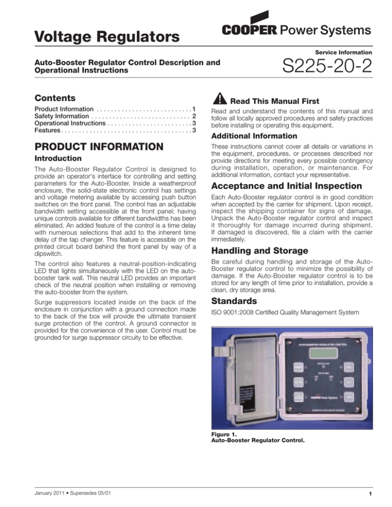
The Auto-Booster Regulator Control is designed to
provide an operator's interface for controlling and setting
parameters for the Auto-Booster. Inside a weatherproof
enclosure, the solid-state electronic control has settings
and voltage metering available by accessing push button
switches on the front panel. The control has an adjustable
bandwidth setting accessible at the front panel; having
unique controls available for different bandwidths has been
eliminated. An added feature of the control is a time delay
with numerous selections that add to the inherent time
delay of the tap changer. This feature is accessible on the
printed circuit board behind the front panel by way of a
dipswitch.
Additional Information
Acceptance and Initial Inspection
Each Auto-Booster regulator control is in good condition
when accepted by the carrier for shipment. Upon receipt,
inspect the shipping container for signs of damage.
Unpack the Auto-Booster regulator control and inspect
it thoroughly for damage incurred during shipment.
If damaged is discovered, file a claim with the carrier
immediately.
Handling and Storage
The control also features a neutral-position-indicating
LED that lights simultaneously with the LED on the autobooster tank wall. This neutral LED provides an important
check of the neutral position when installing or removing
the auto-booster from the system.
Be careful during handling and storage of the AutoBooster regulator control to minimize the possibility of
damage. If the Auto-Booster regulator control is to be
stored for any length of time prior to installation, provide a
clean, dry storage area.
Surge suppressors located inside on the back of the
enclosure in conjunction with a ground connection made
to the back of the box will provide the ultimate transient
surge protection of the control. A ground connector is
provided for the convenience of the user. Control must be
grounded for surge suppressor circuity to be effective.
Standards
ISO 9001:2008 Certified Quality Management System
Figure 1.
Auto-Booster Regulator Control.
January 2011 • Supersedes 05/01
1
Auto-Booster Regulator Control Description and Operational Instructions
!
SAFETY
FOR LIFE
SAFETY FOR LIFE
!
SAFETY
FOR LIFE
Cooper Power Systems products meet or exceed all applicable industry standards relating to product safety. We actively
promote safe practices in the use and maintenance of our products through our service literature, instructional training
programs, and the continuous efforts of all Cooper Power Systems employees involved in product design, manufacture,
marketing and service.
We strongly urge that you always follow all locally approved safety procedures and safety instructions when working
around high-voltage lines and equipment and support our “Safety For Life” mission.
SAFETY Information
The instructions in this manual are not intended as a
sub­s titute for proper training or adequate experience
in the safe operation of the equipment described.
Only competent technicians, who are familiar with this
equipment should install, operate and service it.
A competent technician has these qualifications:
nIs thoroughly familiar with these instructions.
nIs trained in industry-accepted high- and low-voltage
safe operating practices and procedures.
nIs trained and authorized to energize, de-energize, clear,
and ground power distribution equipment.
nIs trained in the care and use of protective equipment
such as flash clothing, safety glasses, face shield, hard
hat, rubber gloves, hotstick, etc.
Following is important safety information. For safe
installation and operation of this equipment, be sure to
read and understand all cautions and warnings.
Hazard Statement Definitions
This manual may contain four types of hazard
statements:
!
DANGER:
Indicates a hazardous situation which, if not
avoided, will result in death or serious injury.
!
WARNING:
Indicates a hazardous situation which, if not
avoided, could result In death or serious injury.
!
CAUTION:
Indicates a hazardous situation which, if not
avoided, could result in minor or moderate injury.
Caution: Indicates a hazardous situation which,
if not avoided, could result in equipment damage
only.
2
Safety Instructions
Following are general caution and warning statements that
apply to this equipment. Additional statements, related to
specific tasks and procedures, are located throughout the
manual.
!
DANGER:
Hazardous voltage. Contact with high voltage will
cause death or severe personal injury. Follow all
locally approved safety procedures when working
around high- and low-voltage lines and equipment.
!
WARNING:
Before installing, operating, maintaining, or testing
this equipment, carefully read and understand
the contents of this manual. Improper operation,
handling or maintenance can result in death, severe
personal injury, and equipment damage.
!
WARNING:
This equipment is not intended to protect human
life. Follow all locally approved procedures and
safety practices when installing or operating this
equipment. Failure to comply may result in death,
severe personal injury and equipment damage.
!
WARNING:
Power distribution and transmission equipment
must be properly selected for the intended
application. It must be installed and serviced
by competent personnel who have been trained
and understand proper safety procedures. These
instructions are written for such personnel and
are not a substitute for adequate training and
experience in safety procedures. Failure to properly
select, install or maintain power distribution and
transmission equipment can result in death, severe
personal injury, and equipment damage.
!
S225-20-2
SAFETY
FOR LIFE
Operational instructions
Field Replacements
Two basic types of the Auto-Booster controls are available
for field replacement. The standard control has a neutral
light providing an important double check of the neutral
position in conjunction with the existing neutral light on
the tank wall. The Auto-Booster must be in the neutral
position when installing or removing it from service. Some
older models of the Auto-Booster do not have the circuitry
available for activating this neutral light on the control. A
special control is available for handling these types of older
models. The surge protection circuit inside on the back of
the enclosure is modified to handle the older circuitry and
the neutral light of the control is masked. Kits are available
for upgrading the obsolete tap changers and circuitry
to incorporate the standard Auto-Booster control with a
neutral light.
The standard control with neutral light, 57A64306600A,
replaces 37C14214500A (AA003), 37C14214500C
(AA005), 37C14214500E (AA006) and 37C14214500G
(AA004). The special control without neutral light,
57A64306600B, replaces 37C14214500B (AA013),
37C14214500D (AA015), 37C14214500F (AA016), and
37C14214500K (AA014).
Features
Control Circuit
The control circuit provides automatic or manual control of
the Auto-Booster. The Raise, Auto and Lower push button
switches establish the interface. In the Auto mode, the
voltage supply from the utility winding of the auto-booster
is compared with the preset values of Set Voltage and
Band-width. If the voltage falls outside the band a time
delay sequence is initiated. At the end of the time delay, a
corrective tap change direction is stated.
Bandwidth
The bandwidth is displayed when this switch is pressed.
The bandwidth can be set for 3.0, 4.0, 5.0 or 6.0 in 1.0
volt increments. Pressing the switch and watching the
value increment can change this value. It will roll over
from 6.0 to 3.0 volts. Once the changed value is selected,
release the switch and the display will blink for two
seconds and then display the new value. This confirms
that the new value is stored in non-volatile memory.
Voltage
RMS Voltage (120-Volt Base) is displayed when this switch
is pressed. The accuracy is +/- 0.2 VAC over the operating
range of 105.0 to 140.0 volts. Test receptacle jacks
are also located externally at the bottom of the control
enclosure. These receptacle jacks are not grounded.
Figure 2.
Auto-Booster Regulator Control Printed Circuit Board.
Set Voltage
The set voltage is displayed when this switch is pressed.
Available operating range is 105.0 to 140.0 volts in 0.1 volt
increments. Pressing and holding in the switch causes the
value to increment. The value will roll over from 140.0 to
105.0 volts. Once the value is selected, release the switch
and the display will blink for two seconds and then display
the new value. This confirms that the new value is stored
in non-volatile memory.
Raise
The Raise shaded coil of the energized tap changer is
shorted and a Raise tap change is initiated when this
switch is activated. Raise tap changes will continue until
the Auto switch is pressed or the Raise switch is pressed
toggling its operation to Auto.
Auto
The control will operate in the Auto mode when this
switch is pressed. In this mode the input control voltage
is monitored. When the control goes out-of-band, the
appropriate Low or High LED is illuminated. If a time delay
has been selected the time out will begin. If the voltage
stays out of band and the time delay times out, the motor
will be energized and a tap change is initiated. If this switch
is pressed and held for three seconds the Auto mode will
be turned off and the display will show "OFF". In this mode
the voltage can go out-of-band and time out but the motor
will not be energized. Pressing the Auto switch will revert
back to the Auto mode of operation.
Lower
The lower shaded coil of the energized tap changer is
shorted and a Lower tap change is initiated when this
switch is activated. Lower tap changes will continue until
the Auto switch is pressed or the Lower switch is pressed
toggling its operation to Auto.
3
Auto-Booster Regulator Control Description and Operational Instructions
Time Delay
Selecting dipswitch positions on the back of the printed
circuit, Figure 2, of 15, 30, 60, and 120 seconds will
program the time delay. This will result in the additive
selections yielding a time delay setting of 0, 15, 30, 45,
60, 75, 90, 105, 120, 135, 150, 165, 180, 195, 210, and
225 seconds. These selections add to the inherent time
delay of 30 seconds due to the spring wind-up of the tap
changer on the first tap change. For example, if a user
selects, via the printed circuit board time delay switches,
a time delay of 15 seconds, the first tap will occur after 45
seconds (30 seconds inherent to the tap changer plus 15
seconds additive time delay) has expired if the voltage had
stayed out of band for 15 seconds.
!
SAFETY
FOR LIFE
© 2011 Cooper Industries. All Rights Reserved.
Cooper Power Systems is a valuable trademark of Cooper Industries in the U.S. and
other countries. You are not permitted to use the Cooper Trademarks without the prior
written permission of Cooper Industries.
S225202 Rev. 1 (Replaces S225202 Rev. 0)
2300 Badger Drive
Waukesha, WI 53188 USA
www.cooperpower.com


