σ Loads M I
advertisement

PRIMARY STRESS ALLOCATION, LOADS AND DESIGN APPROACH
Loads
Primary – hull girder stresses
σ=
My
I
Secondary/Tertiary
Other
Primary – Hull Girder
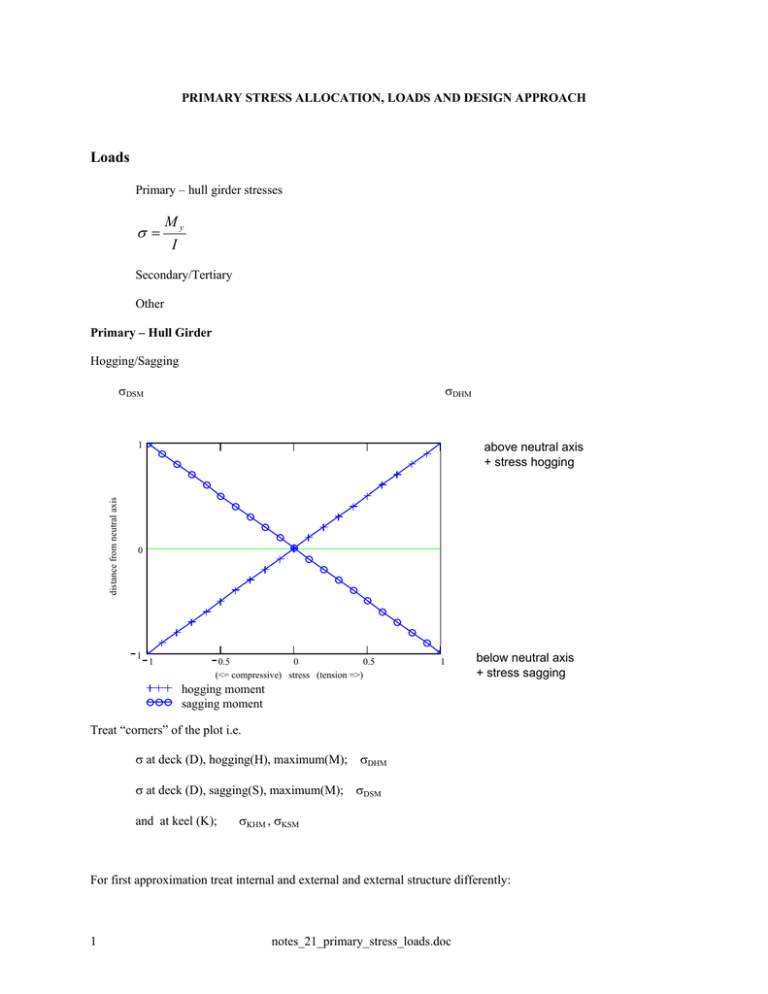
Hogging/Sagging
σDSM
σDHM
distance from neutral axis
1
above neutral axis
+ stress hogging
0
1
1
0.5
0
0.5
(<= compressive) stress (tension =>)
1
below neutral axis
+ stress sagging
hogging moment
sagging moment
Treat “corners” of the plot i.e.
σ at deck (D), hogging(H), maximum(M); σDHM
σ at deck (D), sagging(S), maximum(M); σDSM
and at keel (K);
σKHM , σKSM
For first approximation treat internal and external and external structure differently:
1
notes_21_primary_stress_loads.doc
Internal – linear through 0, 0
External – Design Philosophy governs at least to start
distance from neutral axis
1
0
1
1
0.5
0
0.5
(<= compressive) stress (tension =>)
1
hogging moment
sagging moment
hogging external
sagging external
sagging external
hogging external
first set tension at neutral axis at half the maximum in tension and compression ;
1
2
σ DHM
σ KSM
1
2
σ DSM
σ KHM
σ TNA ≡ max
σ CNA ≡ max
Then linear
Design Philosophy further allocates a fraction of allowable stress to primary
MS
8.5
TSI
19.04 KSI
HTS
9.5
TSI
21.28 KSI
HY-80
10.5
TSI
23.52 KSI
HY-100
11.5
TSI
25.76 KSI
2
notes_21_primary_stress_loads.doc
And applies margin of
1 TSI combatant
0.5 TSI auxiliary and patrol craft
stress allocated to primary
distance from neutraal axis
1
0
1
0
0.5
1 => total allowable stress
1
If required, bending moments could be estimated as follows:
With sufficient knowledge of the design, a bending moment can be calculated (static or stochastic etc.) Frequently to
get started on the design spiral an initial estimate of the structural weight and scantlings is desired. Estimates can be
used for a first estimate. One such approximation derived from a curve fit of 13 destroyer and frigate hulls (used by
Asset) is as follows:
MbH = -0.000457 * L2.5*B longtons*feet
MbS = 0.000381 * L2.5*B longtons*feet
where:
L = length between perpendiculars
B = maximum beam at design waterline
When process starts may not be sufficiently confident to calculate I yy so we cannot estimate σ
Set
σ DHM = σ KSM = σ allow primary max
Use linear relations for interior and exterior – with
3
notes_21_primary_stress_loads.doc
yNA = yD/2
then when first estimate of scantlings are complete, calculate neutral axis, moment of inertia and bending moment
and repeat the process
Review
handout
material properties
plate catalog
stiffener catalog
acronym PSF
Maestro description
Loads table
Loads sketch SNAME
Material properties
Note 1:
allowable working stress
Steel
σy
σy
1 σu
+
ex MS =
1.25
2 2.15 1.25
σ AWS =
actual close for MS
Note 2:
maximum allowable working stress; 13.122 will use
γ S = 1.25
γ C = 1.5
for serviceability
for collapse
Plate/stiffeners – use for future problem sets
Partial Safety Factors
Tabular form – separate by origin and serviceability vs collapse
note yield ≠ collapse
Next page defines words
Outlines where we’re going
4
notes_21_primary_stress_loads.doc
σy
factored by
Design Practice
EXTERNAL stress allocated to primary
INTERNAL stress allocated to primary
1
distance from neutral axis
distance from neutraal axis
1
0
0
1
1
1
0.5
0
0.5
1 => total allowable stress
1
1
1
2
σ DHM
σ KSM
σTNA = 0
1
2
σ DSM
(use – sign for compression)
σ
KHM
σCNA = 0
σ TNA ≡ max
σ CNA ≡ max
1st Iteration
yNA = yD/2
ref. keel
σ DHM = σ KSM =
σ DSM = σ KHM = −
Max Primary Stress (+ => tension)
Max Primary Stress (- => compression)
Relationship (y) is linear
Not necessary but typically expressed such that y (ref keel) to mid ht of panel
treat above and below NA separately
5
0.5
0
0.5
(<= compressive) stress (tension =>)
notes_21_primary_stress_loads.doc
1
Below Neutral axis EXTERNAL:
σT(y) = σTNA + (σKSM -σTNA)*(yNA-y)/yNA
σC(y) = σCNA + (σKHM -σCNA)*(yNA-y)/yNA
Above Neutral axis EXTERNAL:
σT(y) = σTNA + (σDHM -σTNA)*(y-yNA)/yNA
σC(y) = σCNA + (σDSM -σCNA)*(y-yNA)/yNA
INTERNAL:
Then:
above with σTNA = σCNA = 0
Maximum Stress = σMAX(y) = MAX{σT(y), -σC(y)}
Have talked about mechanism for hull girder shear and bending
wt – buoyancy distribution in still water or wave induced
Will now consider relationships as they relate to other than primary bending effects
Secondary loads:
Many ways to classify, we will use
Sea & Weather and
Individual
wave *
live
green sea
dead
heel *
damage (* heel)
slap
We will ignore: e.g. pitch *
blast missile on deck > acceleration *
underwater on hull _ pressure
slamming
6
notes_21_primary_stress_loads.doc
ice, snow, wind
equipment weight *
* Maestro includes explicitly
others are input as pressures on strake
13.122 Design Loads (all expressed in ht of sea water pressure (feet))
Weather (choose largest – where applicable)
Wave
Hwv = yDWL + 0.55√L - y
Notes: only + Hwv
ignoring phase
ignoring adjustment of yDWL due to dynamic effects
“Smith” effect
wave dynamics > exponential pressure
decay with depth
Maestro includes to a degree
Heel
HH = (yDWL – y + z*tan(α) ) * cos(α)
Set α = 30°for design
z*tan(α
α
y
α
yDWL-y
z
HH = (yDWL – y +z*tan(α)) * cos(α)
7
notes_21_primary_stress_loads.doc
Green seas (applicable to Weather Deck WD)
4
8-12
0
x
FP
A
≡ 8 to 12 submerged at FP linearly decreasing to constant 4’ over weather deck => 13.122 use 8 ft
H GS
yo − y + 4ft
= max yo + 8
L
2
x − − y
2
L
Wave Slap
Design value 500 psf > converted to height in feet => 500/64 lbs/ft^3 = 7.82 feet
Completes weather and sea
H SW = max [ HWV , H H , HWS ]
Independent
Live Load
varies from 75 psf for living space Mezzanine Deck and up
100 psf living space below Mezzanine Deck
150 psf offices and control spaces below Mezzanine Deck
to 300 psf for storerooms/magazine
Use 150 psf => HLL = 150/64 lbs/ft^3 = 2.37 feet
Damage (Internal structure horizontal and vertical)
Flooding occurs to margin line might be worsened with heel
Design approach (decks only)
Compare flooded pressure with heel = 30° Margin line at deck
8
notes_21_primary_stress_loads.doc
to that panel being flooded without heel
Margin line at deck (yD – y)
as with heel yDWL replaced by yD
Set α = 30°
HDAM = MAX{(yD+z*tan(α) – y) * cos(α), (yD – y)}
Dead load
Weight of fixed structure
1” thick 1 ft2 plate weighs ~ 40 lbs
Design: Use approximately 2.5 times plate thickness
HDL = 40 * 2.5 /64 *t = 1.72 * t in feet
Where t = plate thickness in inches
One other criteria: maximum stiffener spacing
maximum b =
B
(breadth of plate)
N +1
23 ≤ b ≤ 28
b = stiffener spacing
N = number of stiffeners
Review
Look at Handout
Sea/Weather check applicability
use largest
Independent apply as appropriate
9
notes_21_primary_stress_loads.doc


