Greengate
Technical Data
CKM18, CKM36 & CKM48
ControlKeeper M
Catalog#
Prepared by
Project
Date
Comments
Type
Overview
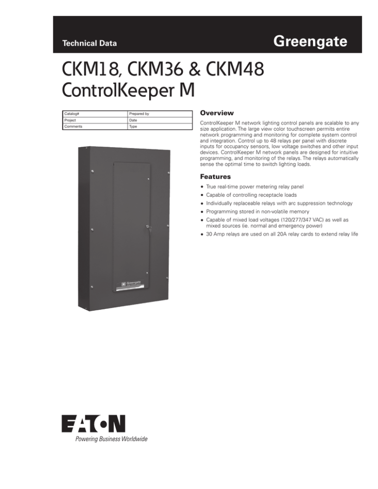
ControlKeeper M network lighting control panels are scalable to any
size application. The large view color touchscreen permits entire
network programming and monitoring for complete system control
and integration. Control up to 48 relays per panel with discrete
inputs for occupancy sensors, low voltage switches and other input
devices. ControlKeeper M network panels are designed for intuitive
programming, and monitoring of the relays. The relays automatically
sense the optimal time to switch lighting loads.
Features
True real-time power metering relay panel
Capable of controlling receptacle loads
Individually replaceable relays with arc suppression technology
Programming stored in non-volatile memory
Capable of mixed load voltages (120/277/347 VAC) as well as
mixed sources (ie. normal and emergency power)
30 Amp relays are used on all 20A relay cards to extend relay life
CKM18, CKM36 & CKM48 ControlKeeper M
June 2015
Transformer
Ratings
Power Use
Fully loaded panel 90 watts
Ratings
Operating
Temperature: 32°F to 122°F (0°C to 50°C)
Environment
Master Override ON/AUTO/OFF or Individual relay control with status
LED
Programming
Onboard TouchScreen Interface
One panel or entire network
Optional PC Software
Standard Relay Normally open
Ratings
20A, incandescent 120 VAC, ballast 277 VAC
Maximum wire size: 8 AWG
1HP @ 120 VAC, 2HP @ 277 VAC
Latching Relay
Normally open, normally closed latching
Ratings
20A,120/277 VAC
15A, 347 VAC
Maximum wire size: 8 AWG
1HP @ 120 VAC, 2HP @ 277 VAC
Two Pole Relay Normally open
Ratings
Maximum wire size: 6 AWG
20A, 208, 240/480 VAC
Relays have a minimum 25K SCCR
Standards
UL Approval
UL 508 Listed
UL 924 with LRM
Automation Interface Module
Keeper Enterprise Software
Ethernet Interface Module
Digital Switch
Dry Contact Switches
Occupancy & Daylighting Sensors
Dimensions
Enclosure
CKM 18: 31”H X 24”W X 6”D (up to 18 relays)
CKM 36: 40”H X 24”W X 6”D (up to 36 relays)
24 in.
(609.6 mm)
24 in.
(609.6 mm)
System Includes
24 in.
(609.6 mm)
Digital Switch interface
6 in.
(152.4 mm)
0-10V inputs
Time schedules with astronomic clock
(152.4 mm)
Timed inputs
Occupant warn-off and overrides
31 in. (787.4 mm)
Power Metering
Onboard Ethernet port
UL Listed - UL 924 with LRM
www.eaton.com/lightingsystems
40 in. (1016 mm)
mm)
Prioritization and masking (609.6
of switch
inputs, time schedules and
remotes
48.25 in. (1225.55 mm)
Controls receptacle loads with
6 in. module
24 in. latching relay
2
6 in.
(152.4 mm)
24 in.
(609.6 mm)
NEMA 1 enclosure
Low Voltage input connections
24
(609
CKM 48: 48.25”H X 24”W X 6”D (up to 48 relays)
6 in.
(152.4 mm)
48.25 in. (1225.55 mm)
NEMA 1 surface mount, lockable
CKM18: 31”H X 24”W X 6”D (up to 18 relays)
CKM36: 40”H X 24”W X 6”D (up to 36 relays)
CKM48: 48.25”H X 24”W X 6”D (up to 48 relays)
Wide input voltage power supply, 120-347 VAC
40 in. (1016 mm)
Enclosure
Size
Accessories
31 in. (787.4 mm)
Specifications
6 in.
(152.4 mm)
CKM18, CKM36 & CKM48 ControlKeeper M
June 2015
Wiring Diagram
Latching Relay Receptacle Control
Sample One-Line
Zone 1
Zone 2
Zone 3
Zone 4
GDS Cable type: Cooper
LCCNP or Cooper LCCP
or Belden 1502, maximum
distance 1000 feet per
GDS network
Zone 1
Zone 2
Zone 3
Zone 4
Zone 5
Zone 5
Zone 6
Zone 6
ControlKeeper M Relay
Panel Power Metering
Zone 1
Zone 2
Zone 3
ControlKeeper M
Relay Panel
Power Metering
Zone 1
ControlKeeper T
Relay Panel
Zone 2
Zone 3
Zone 4
Zone 4
Zone 5
Zone 5
Zone 6
Zone 6
ControlKeeper 4A
Distributed 0-10V
Dimming panel
Q1
SW1
X4 SRC
PCI 2005
LINE
8
C1
LED1
7
LOAD
6
C
C5
LED5
50-022110-01
DIGITA
CAN-TX
K1
5
Q2
4
U4
TB2
3
LED4
U2
MOV2
2
CAN-RX
TB1
54-022510-
SW2
1
MOV1
50-022510-00
ADDRESS
LED3
ALL ON
SW2
LED2
ALL OFF
PCI-NET
LINE
LED1
NETWORK
RS-232
K2
Q3
RSC PIC
MOV3
SWIN PIC
C14
TB3
U6
U2
K3
RSC STAT
MOV4
L1
PE-52627
PE-52647
or
Talema
SWV-0-90-330
LED9
LINE
LOAD
SW4
U3
U4
LED7
STATUS
SD1
Gnd
K4
1
0 OHM
OPT-47K
RESET PICS
TB4
LED5
LOAD
SW3
LINE
RS-232-SP
PCI-NET TERM
Q4
To other lighting control panels
LED3
U1
LOAD
1
+NET -NET
SWIN STAT
1
LED8
POWER
TB2
J7
LOCAL
REMOTE
Ethernet link:
Programming access or
Power Metering data access
PCI-NET
Ethernet link:
Programming access or
Power Metering data access
J8
ANALOG INPUTS
TB3
ANALOG INPUTS
+24 GND
AN AN AN AN
1
2
3 4
ANALOG GND
TB4
DIMMING OUTPUTS
DIMMING OUTPUTS
DO RTN DO RTN DO RTN
1 1
2 2
3 3
SWITCH INPUTS
TB5
TB6
LSO TEST
SWITCH INPUTS AND LIGHTED SWITCH OUTS
DO RTN IN +24
4 4
1
IN LS
2
1
IN +24 IN LS
3
4 2
TP1
IN +24 IN LS IN
5
6 3 7
+24
IN
8
LS
4
To other lighting control panels
Cable type: Belden 9841 or equal
Maximum distance 4000 feet per network
www.eaton.com/lightingsystems
3
CKM18, CKM36 & CKM48 ControlKeeper M
June 2015
Ordering
This is a network-ready lighting control system. It can be combined
with other ControlKeeper series panels to create a scalable
networked lighting control scheme. It can be ordered with any
suitable system option or accessory.
CKM - 18 - 6 - 5 - 2 - S - T - CCM1 - AN1
Product
Analogs
CKM= ControlKeeper M
0, AN1, AN2
= 18 Size
0, AN1, AN2, AN3, AN4
= 36 Size
0, AN1, AN2, AN3, AN4, AN5, AN6 = 48 Size
(Dependent upon # of CCM’s, two AN’s for each
CCM. Each AN supplies four analog 0-10V inputs)
Panel Size
18 = 18 Size
36 = 36 Size
48 = 48 Size
Inputs (Each CCM supplies 18 Contact Inputs
0, CCM1
= 18 Size
0, CCM1, CCM2
= 32 Size
0, CCM1, CCM2, CCM3 = 48 Size
# of Latching Relays (Single Space)
0-18 = 0-18 for 18 Size panel
0-36 = 0-36 for 36 Size panel
0-48 = 0-48 for 48 Size panel
Display
# of Electrically Held Relays (Single Space)
0-18 = 0-18 for 18 Size panel
0-36 = 0-36 for 36 Size panel
0-48 = 0-48 for 48 Size panel
NT = No TouchScreen
T = TouchScreen
Enclosure
S = Surface
# of Two Pole Relays (Single Space)
0-8 = 0-8 for 18 Size panel
0-18 = 0-18 for 36 Size panel
0-24 = 0-24 for 48 Size panel
Additional Options
Catalog #
Description
iBarrier
Individual Relay Barrier, Voltage and Power Source Separation
Eaton
1000 Eaton Boulevard
Cleveland, OH 44122
United States
Eaton.com
Eaton
Lighting Systems – Controls Products
203 Cooper Circle
Peachtree City, GA 30269
www.eaton.com/lightingsystems
© 2015 Eaton
All Rights Reserved
Printed in USA
Publication No. TD503010EN
June 8, 2015
Eaton is a registered trademark.
All other trademarks are property
of their respective owners.


