Integrated Modeling of Physical System Dynamics © Neville Hogan 1994 page 1
advertisement
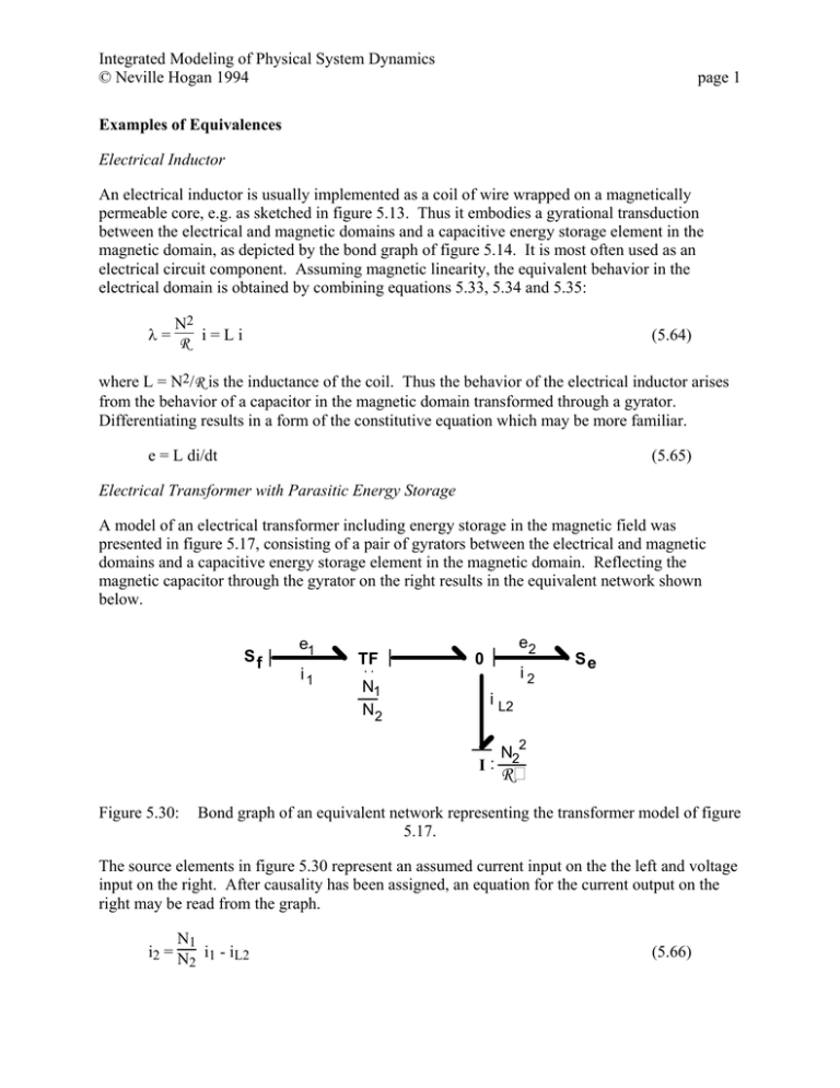
Integrated Modeling of Physical System Dynamics © Neville Hogan 1994 page 1 Examples of Equivalences Electrical Inductor An electrical inductor is usually implemented as a coil of wire wrapped on a magnetically permeable core, e.g. as sketched in figure 5.13. Thus it embodies a gyrational transduction between the electrical and magnetic domains and a capacitive energy storage element in the magnetic domain, as depicted by the bond graph of figure 5.14. It is most often used as an electrical circuit component. Assuming magnetic linearity, the equivalent behavior in the electrical domain is obtained by combining equations 5.33, 5.34 and 5.35: N2 λ= R i=Li (5.64) where L = N2/R is the inductance of the coil. Thus the behavior of the electrical inductor arises from the behavior of a capacitor in the magnetic domain transformed through a gyrator. Differentiating results in a form of the constitutive equation which may be more familiar. e = L di/dt (5.65) Electrical Transformer with Parasitic Energy Storage A model of an electrical transformer including energy storage in the magnetic field was presented in figure 5.17, consisting of a pair of gyrators between the electrical and magnetic domains and a capacitive energy storage element in the magnetic domain. Reflecting the magnetic capacitor through the gyrator on the right results in the equivalent network shown below. Sf e1 i1 TF N1 N2 e2 0 i2 i L2 I: Figure 5.30: Se N22 R Bond graph of an equivalent network representing the transformer model of figure 5.17. The source elements in figure 5.30 represent an assumed current input on the the left and voltage input on the right. After causality has been assigned, an equation for the current output on the right may be read from the graph. N1 i2 = N i1 - iL2 2 (5.66) Integrated Modeling of Physical System Dynamics © Neville Hogan 1994 page 2 where iL2 is the inductor current, determined from the inductor constitutive equation expressed in integral causal form. diL2 N22 dt = R e2 (5.67) Differentiating equation 5.66 and substituting equation 5.67 yields equation 5.45 as before. Alternatively, the magnetic capacitor could also be transformed through the gyrator on the left of figure 5.17. The resulting equivalent network is shown below. Sf e1 i1 0 TF i L1 I: Figure 5.31: N1 N2 e2 i2 Se N12 R Bond graph of an alternative equivalent network representing the transformer model of figure 5.17. The same network could be obtained by transforming the inductor of figure 5.30 through the transformer. Consequently, the values of the two equivalent inductors should be related by the square of the transformer coefficient, and they are. N12 ⎡N1⎤ 2 N22 ⎡N1⎤ 2 L1 = R = ⎢N ⎥ R = ⎢N ⎥ L2 (5.68) ⎣ 2⎦ ⎣ 2 ⎦
