2.141 Modeling and Simulation of Dynamic Systems Assignment #5 Problem 1
advertisement
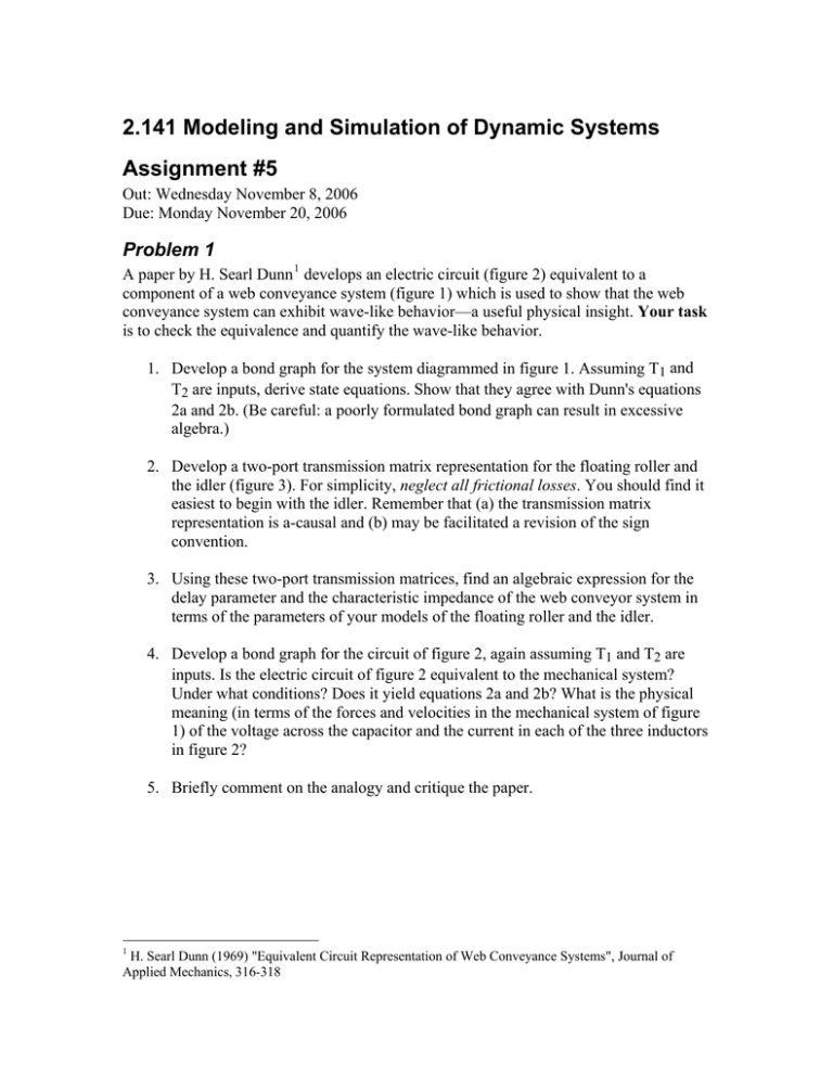
2.141 Modeling and Simulation of Dynamic Systems Assignment #5 Out: Wednesday November 8, 2006 Due: Monday November 20, 2006 Problem 1 A paper by H. Searl Dunn 1 develops an electric circuit (figure 2) equivalent to a component of a web conveyance system (figure 1) which is used to show that the web conveyance system can exhibit wave-like behavior—a useful physical insight. Your task is to check the equivalence and quantify the wave-like behavior. 1. Develop a bond graph for the system diagrammed in figure 1. Assuming T1 and T2 are inputs, derive state equations. Show that they agree with Dunn's equations 2a and 2b. (Be careful: a poorly formulated bond graph can result in excessive algebra.) 2. Develop a two-port transmission matrix representation for the floating roller and the idler (figure 3). For simplicity, neglect all frictional losses. You should find it easiest to begin with the idler. Remember that (a) the transmission matrix representation is a-causal and (b) may be facilitated a revision of the sign convention. 3. Using these two-port transmission matrices, find an algebraic expression for the delay parameter and the characteristic impedance of the web conveyor system in terms of the parameters of your models of the floating roller and the idler. 4. Develop a bond graph for the circuit of figure 2, again assuming T1 and T2 are inputs. Is the electric circuit of figure 2 equivalent to the mechanical system? Under what conditions? Does it yield equations 2a and 2b? What is the physical meaning (in terms of the forces and velocities in the mechanical system of figure 1) of the voltage across the capacitor and the current in each of the three inductors in figure 2? 5. Briefly comment on the analogy and critique the paper. 1 H. Searl Dunn (1969) "Equivalent Circuit Representation of Web Conveyance Systems", Journal of Applied Mechanics, 316-318 Problem 2 Transmission matrices (introduced to model wave-like behavior) may also be applied to model diffusion. In assignment 2 you modeled the transduction behavior of an ElectroActive Polymer Actuator based on PolyPyrrole (PPY). In this problem you are to model its electrical dynamics. Immersed in an ionic solution, applying a voltage between PPY and a “counter electrode” induces an accumulation of charged ions adjacent to the material surface and a subsequent diffusion of ions into the material. Bowers 2 presents a simplified electrical circuit model of the electrochemical process shown in figure 1. Contact Resistance Polymer Resistance + Volumetric Capacitance Double Layer Capacitance Diffusion Resistance Vin Electrolyte Resistance Counter Electrode Double Layer Capacitance - Figure 1: Basic Structure of EAP Electrochemical Circuit However, the ionic diffusion process is better represented by a continuum model (i.e., based on partial differential equations). Madden3 developed the following continuumbased model of the admittance of a free-standing polymer film: ⎛a s ⎞ ⋅ tanh ⎜ ⋅ ⎟+ s 2 D⎠ δ s ⎝ Y (s) = R s ⎛a 3 D s ⎞ s ⋅ tanh ⎜ ⋅ +s 2 + ⎟ RC δ ⎝2 D⎠ D where s is the Laplace variable, R is the total resistance of the circuit, C is the total volumetric capacitance, D is a coefficient characterizing the speed of diffusion, δ is the width of the double layer gap, and a is the thickness of the polymer. The circuit and continuum models are compared in figure 2 using Madden’s parameters: R = 31 Ω, cV = 1.3×10⁸ F/m3, D = 2.1×10⁻¹² m2/s, δ = 2 nm and a = 8.5 μm. 2 Bowers, Thomas A. (2004) Modeling, Simulation, and Control of a Polypyrrole-Based Conducting Polymer Actuator S.M. Thesis , MIT Mechanical Engineering. 3 Madden, John D. W. (2000) Conducting Polymer Actuators, Ph.D. Thesis, MIT Mechanical Engineering. 2 10 Admittance (S) 10 10 10 10 -1 Frequency Response of Polypyrrole Admittance: D=2.1 μm /s, δ =2 nm, R=31 Ω -2 -3 -4 -5 Continuum Diffusion Model Electrochemical Circuit Model Phase (deg) 100 50 0 -50 -4 10 10 -2 0 10 Frequency (Hz) 10 2 10 4 Figure 2: Circuit and Continuum Models of Polypyrrole Admittance Your task is to develop a reticulated network model of the diffusion process as depicted in figure 3 and compare it with the continuum model. Polymer Volume Diffusion Element Polymer Double Layer Polymer Surface Figure 3: Reticulation of Thin-Film Polymer into Diffusion Elements 1. Develop a two-port transmission matrix corresponding to each diffusion “compartment” or element. 2. Use it to show that, for a large number of elements, the reticulated model converges to the continuum model. 3. Using two compartments, compare the admittance of the reticulated network model with that of the continuum model.
