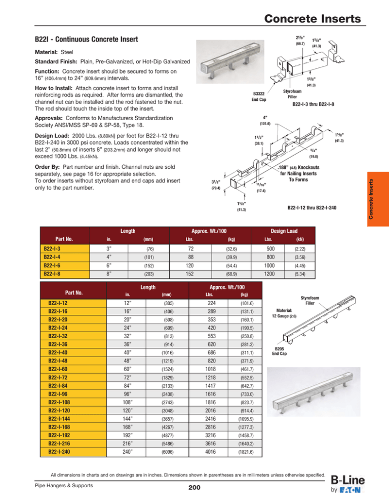
Length Approx. Wt./100 Design Load Part No.
advertisement

Concrete Inserts 25/8” B22I - Continuous Concrete Insert (66.7) 15/8” (41.3) Material: Steel Standard Finish: Plain, Pre-Galvanized, or Hot-Dip Galvanized Function: Concrete insert should be secured to forms on 16” (406.4mm) to 24” (609.6mm) intervals. 15/8” (41.3) How to Install: Attach concrete insert to forms and install reinforcing rods as required. After forms are dismantled, the channel nut can be installed and the rod fastened to the nut. The rod should touch the inside top of the insert. Styrofoam Filler B3322 End Cap B22-I-3 thru B22-I-8 Approvals: Conforms to Manufacturers Standardization Society ANSI/MSS SP-69 & SP-58, Type 18. 4” (101.6) Design Load: 2000 Lbs. (8.89kN) per foot for B22-I-12 thru B22-I-240 in 3000 psi concrete. Loads concentrated within the last 2” (50.8mm) of inserts 8” (203.2mm) and longer should not exceed 1000 Lbs. (4.45kN). 15/8” 11/2” (41.3) (38.1) 3/4” Order By: Part number and finish. Channel nuts are sold separately, see page 16 for appropriate selection. To order inserts without styrofoam and end caps add insert only to the part number. .188” (4.8) Knockouts for Nailing Inserts To Forms 31/8” 11/16” (79.4) (17.4) 15/8” B22-I-12 thru B22-I-240 (41.3) Length Part No. B22-I-3 B22-I-4 B22-I-6 B22-I-8 in. 3” 4” 6” 8” Approx. Wt./100 Lbs. (kg) Lbs. (kN) (76) 72 88 120 152 (32.6) 500 800 1000 1200 (2.22) (101) (152) (203) Length Part No. B22-I-12 B22-I-16 B22-I-20 B22-I-24 B22-I-32 B22-I-36 B22-I-40 B22-I-48 B22-I-60 B22-I-72 B22-I-84 B22-I-96 B22-I-108 B22-I-120 B22-I-144 B22-I-168 B22-I-192 B22-I-216 B22-I-240 in. 12” 16” 20” 24” 32” 36” 40” 48” 60” 72” 84” 96” 108” 120” 144” 168” 192” 216” 240” Design Load (mm) (39.9) (54.4) (68.9) (3.56) (4.45) (5.34) Approx. Wt./100 (mm) (305) (406) (508) (609) (813) (914) (1016) (1219) (1524) (1829) (2133) (2438) (2743) (3048) (3657) (4267) (4877) (5486) (6096) Lbs. (kg) 224 289 353 420 553 620 686 820 1018 1218 1417 1616 1816 2016 2416 2816 3216 3616 4016 (101.6) (131.1) (160.1) Styrofoam Filler Material: 12 Gauge (2.6) (190.5) (250.8) (281.2) (311.1) B205 End Cap (371.9) (461.7) (552.5) (642.7) (733.0) (823.7) (914.4) (1095.9) (1277.3) (1458.7) (1640.2) (1821.6) All dimensions in charts and on drawings are in inches. Dimensions shown in parentheses are in millimeters unless otherwise specified. Pipe Hangers & Supports 200 Concrete Inserts (19.0) Concrete Inserts 25/8” B32I - Continuous Concrete Insert 15/8” (66.7) (41.3) Material: Steel Standard Finish: Plain, Pre-Galvanized, or Hot-Dip Galvanized Function: Concrete insert should be secured to forms on 16” (406.4mm) to 24” (609.6mm) intervals. 13/8” (34.9) How to Install: Attach concrete insert to forms and install reinforcing rods as required. After forms are dismantled, the channel nut can be installed and the rod fastened to the nut. The rod should touch the inside top of the insert. B3332 End Cap B32-I-3 thru B32-I-8 Approvals: Conforms to Manufacturers Standardization Society ANSI/MSS SP-69 & SP-58, Type 18. 4” (101.6) Design Load: 2000 Lbs. (8.89kN) per foot for B32-I-12 thru B32-I-240 in 3000 psi concrete. Loads concentrated within the last 2” (50.8mm) of inserts 8” (203.2mm) and longer should not exceed 1000 Lbs. (4.45kN). Concrete Inserts Order By: Part number and finish. Channel nuts are sold separately, see page 16 for appropriate selection. To order inserts without styrofoam and end caps add insert only to the part number. 15/8” 11/2” (41.3) (38.1) 3/4” (19.0) .188” (4.8) Knockouts for Nailing Inserts To Forms 27/8” 11/16” (73.0) (17.4) 13/8” B32-I-12 thru B32-I-240 (34.9) Length Part No. in. B32-I-3 B32-I-4 B32-I-6 B32-I-8 3” 4” 6” 8” Approx. Wt./100 Lbs. (kg) Lbs. (kN) (76) 65 80 108 137 (29.5) 500 800 1000 1200 (2.22) (101) (152) (203) B32-I-12 B32-I-16 B32-I-20 B32-I-24 B32-I-32 B32-I-36 B32-I-40 B32-I-48 B32-I-60 B32-I-72 B32-I-84 B32-I-96 B32-I-108 B32-I-120 B32-I-144 B32-I-168 B32-I-192 B32-I-216 B32-I-240 in. 12” 16” 20” 24” 32” 36” 40” 48” 60” 72” 84” 96” 108” 120” 144” 168” 192” 216” 240” Design Load (mm) Length Part No. Styrofoam Filler (36.3) (49.0) (62.1) (3.56) (4.45) (5.34) Approx. Wt./100 (mm) (305) (406) (508) (609) (813) (914) (1016) (1219) (1524) (1829) (2133) (2438) (2743) (3048) (3657) (4267) (4877) (5486) (6096) Lbs. 202 262 316 376 496 556 616 736 915 1095 1274 1453 1633 1813 2173 2533 2893 3253 3613 (kg) Styrofoam Filler (91.6) (118.8) (143.3) Material: 12 Gauge (2.6) (170.5) (225.0) (252.2) (279.4) B206 End Cap (333.8) (415.0) (496.7) (577.9) (659.0) (740.7) (822.3) (985.6) (1148.9) (1312.2) (1475.5) (1638.8) All dimensions in charts and on drawings are in inches. Dimensions shown in parentheses are in millimeters unless otherwise specified. 201 Pipe Hangers & Supports Concrete Inserts 29/16” B52I - Continuous Concrete Insert 15/8” (65.1) (41.3) Material: Steel Standard Finish: Plain, Pre-Galvanized, or Hot-Dip Galvanized Function: Concrete insert should be secured to forms on 16” (406.4mm) to 24” (609.6mm) intervals. 13/16” (20.6) How to Install: Attach concrete insert to forms and install reinforcing rods as required. After forms are dismantled, the channel nut can be installed and the rod fastened to the nut. The rod should touch the inside top of the insert. B3352 End Cap Styrofoam Filler B52-I-3 thru B52-I-8 Approvals: Conforms to Manufacturers Standardization Society ANSI/MSS SP-69 & SP-58, Type 18. 4” (101.6) Design Load: 1500 Lbs. (6.67kN) per foot for B52-I-12 thru B52-I-240 in 3000 psi concrete. Loads concentrated within the last 2” (50.8mm) of inserts 8” (203.2mm) and longer should not exceed 750 Lbs. (3.33kN). 15/8” 11/2” (41.3) (38.1) 3/4” .188” (4.8) Knockouts for Nailing Inserts To Forms 25/16” 11/16” (58.7) (17.4) 13/16” B52-I-12 thru B52-I-240 (20.6) Length Part No. B52-I-3 B52-I-4 B52-I-6 B52-I-8 in. 3” 4” 6” 8” Approx. Wt./100 Lbs. (kg) Lbs. (kN) (76) 53 63 85 106 (24.0) 400 500 750 1000 (1.78) (101) (152) (203) Length Part No. B52-I-12 B52-I-16 B52-I-20 B52-I-24 B52-I-32 B52-I-36 B52-I-40 B52-I-48 B52-I-60 B52-I-72 B52-I-84 B52-I-96 B52-I-108 B52-I-120 B52-I-144 B52-I-168 B52-I-192 B52-I-216 B52-I-240 in. 12” 16” 20” 24” 32” 36” 40” 48” 60” 72” 84” 96” 108” 120” 144” 168” 192” 216” 240” Design Load (mm) (28.6) (38.5) (48.1) (2.22) (3.33) (4.45) Approx. Wt./100 (mm) Lbs. 157 202 237 282 373 419 464 556 692 829 965 1107 1237 1374 1648 1922 2196 2470 2744 (305) (406) (508) (609) (813) (914) (1016) (1219) (1524) (1829) (2133) (2438) (2743) (3048) (3657) (4267) (4877) (5486) (6096) (kg) (71.2) Styrofoam Filler (91.6) (107.5) (127.9) Material: 12 Gauge (2.6) (169.2) (190.0) (210.4) (252.2) B220 End Cap (313.9) (376.0) (437.7) (502.1) (561.1) (623.2) (747.5) (871.8) (996.1) (1120.4) (1244.6) All dimensions in charts and on drawings are in inches. Dimensions shown in parentheses are in millimeters unless otherwise specified. Pipe Hangers & Supports 202 Concrete Inserts (19.0) Order By: Part number and finish. Channel nuts are sold separately, see page 16 for appropriate selection. To order inserts without styrofoam and end caps add insert only to the part number.


