Cable Tray Thermal Contraction and Expansion
advertisement

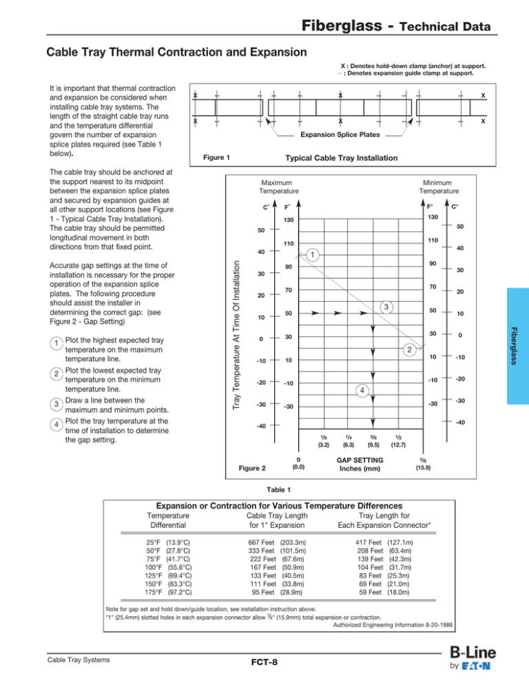
Fiberglass - Technical Data Cable Tray Thermal Contraction and Expansion X : Denotes hold-down clamp (anchor) at support. _ : Denotes expansion guide clamp at support. It is important that thermal contraction and expansion be considered when installing cable tray systems. The length of the straight cable tray runs and the temperature differential govern the number of expansion splice plates required (see Table 1 below). X -- -- -- -- X -- -- -- -- X X -- -- -- -- X -- -- -- -- X Expansion Splice Plates Figure 1 Typical Cable Tray Installation The cable tray should be anchored at the support nearest to its midpoint between the expansion splice plates and secured by expansion guides at all other support locations (see Figure 1 - Typical Cable Tray Installation). The cable tray should be permitted longitudinal movement in both directions from that fixed point. Minimum Temperature F° F° C° 130 130 50 50 110 110 40 40 1 90 90 30 30 70 70 20 3 50 50 10 0 30 -10 10 -20 -10 30 0 10 -10 -10 -20 -30 -30 4 -30 -30 -40 -40 1/8 (3.2) 0 (0.0) 1/4 (6.3) 3/8 (9.5) 1/2 (12.7) GAP SETTING Inches (mm) 5/8 (15.9) Table 1 Expansion or Contraction for Various Temperature Differences 25°F 50°F 75°F 100°F 125°F 150°F 175°F (13.9°C) (27.8°C) (41.7°C) (55.6°C) (69.4°C) (83.3°C) (97.2°C) Cable Tray Length for 1" Expansion 667 Feet 333 Feet 222 Feet 167 Feet 133 Feet 111 Feet 95 Feet (203.3m) (101.5m) (67.6m) (50.9m) (40.5m) (33.8m) (28.9m) Tray Length for Each Expansion Connector* 417 Feet 208 Feet 139 Feet 104 Feet 83 Feet 69 Feet 59 Feet (127.1m) (63.4m) (42.3m) (31.7m) (25.3m) (21.0m) (18.0m) Note for gap set and hold down/guide location, see installation instruction above. *1" (25.4mm) slotted holes in each expansion connector allow 5⁄8" (15.9mm) total expansion or contraction. Authorized Engineering Information 8-20-1986 Cable Tray Systems 10 2 Figure 2 Temperature Differential 20 FCT-8 Fiberglass 1 Plot the highest expected tray temperature on the maximum temperature line. 2 Plot the lowest expected tray temperature on the minimum temperature line. 3 Draw a line between the maximum and minimum points. 4 Plot the tray temperature at the time of installation to determine the gap setting. C° Tray Temperature At Time Of Installation Accurate gap settings at the time of installation is necessary for the proper operation of the expansion splice plates. The following procedure should assist the installer in determining the correct gap: (see Figure 2 - Gap Setting) Maximum Temperature


