Series 2, 3, 4, & 5 Aluminum - Specifications
advertisement
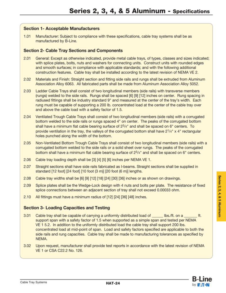
Series 2, 3, 4, & 5 Aluminum - Specifications Section 1- Acceptable Manufacturers 1.01 Manufacturer: Subject to compliance with these specifications, cable tray systems shall be as manufactured by B-Line. Section 2- Cable Tray Sections and Components General: Except as otherwise indicated, provide metal cable trays, of types, classes and sizes indicated; with splice plates, bolts, nuts and washers for connecting units. Construct units with rounded edges and smooth surfaces; in compliance with applicable standards; and with the following additional construction features. Cable tray shall be installed according to the latest revision of NEMA VE 2. 2.02 Materials and Finish: Straight section and fitting side rails and rungs shall be extruded from Aluminum Association Alloy 6063. All fabricated parts shall be made from Aluminum Association Alloy 5052. 2.03 Ladder Cable Trays shall consist of two longitudinal members (side rails) with transverse members (rungs) welded to the side rails. Rungs shall be spaced [6] [9] [12] inches on center. Rung spacing in radiused fittings shall be industry standard 9" and measured at the center of the tray’s width. Each rung must be capable of supporting a 200 lb. concentrated load at the center of the cable tray over and above the cable load with a safety factor of 1.5. 2.04 Ventilated Trough Cable Trays shall consist of two longitudinal members (side rails) with a corrugated bottom welded to the side rails or rungs spaced 4" on center. The peaks of the corrugated bottom shall have a minimum flat cable bearing surface of 23/4" and shall be spaced on 6" centers. To provide ventilation in the tray, the valleys of the corrugated bottom shall have 21/4" x 4" rectangular holes punched along the width of the bottom. 2.05 Non-Ventilated Bottom Trough Cable Trays shall consist of two longitudinal members (side rails) with a corrugated bottom welded to the side rails or a solid sheet over rungs. The peaks of the corrugated bottom shall have a minimum flat cable bearing surface of 23/4" and shall be spaced on 6" centers. 2.06 Cable tray loading depth shall be [3] [4] [5] [6] inches per NEMA VE 1. 2.07 Straight sections shall have side rails fabricated as I-beams. Straight sections shall be supplied in standard [12 foot] [24 foot] [10 foot (3 m)] [20 foot (6 m)] lengths. 2.08 Cable tray widths shall be [6] [9] [12] [18] [24] [30] [36] inches or as shown on drawings. 2.09 Splice plates shall be the Wedge-Lock design with 4 nuts and bolts per plate. The resistance of fixed splice connections between an adjacent section of tray shall not exceed 0.00033 ohm. 2.10 All fittings must have a minimum radius of [12] [24] [36] [48] inches. Section 3- Loading Capacities and Testing 3.01 Cable tray shall be capable of carrying a uniformly distributed load of ______ lbs./ft. on a _______ ft. support span with a safety factor of 1.5 when supported as a simple span and tested per NEMA VE 1 5.2. In addition to the uniformly distributed load the cable tray shall support 200 lbs. concentrated load at mid-point of span. Load and safety factors specified are applicable to both the side rails and rung capacities. Cable tray shall be made to manufacturing tolerances as specified by NEMA. 3.02 Upon request, manufacturer shall provide test reports in accordance with the latest revision of NEMA VE 1 or CSA C22.2 No. 126. Cable Tray Systems HAT-24 Series 2, 3, 4, & 5 Aluminum 2.01

