Lecture Notes on Geometrical Optics (02/18/14)
2.71/2.710 Introduction to Optics –Nick Fang
Outline:
A. Optical Invariant
B. Composite Lenses
C. Ray Vector and Ray Matrix
D. Location of Principal Planes for an Optical System
E. Aperture Stops, Pupils and Windows
A. Optical Invariant
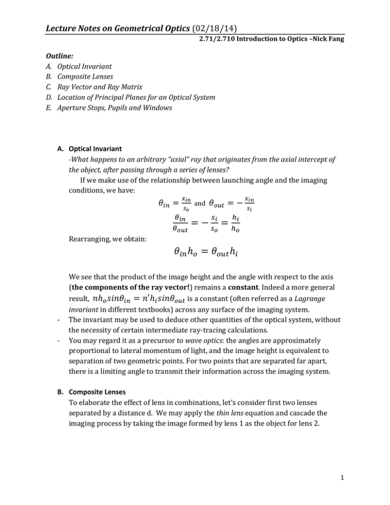
-What happens to an arbitrary “axial” ray that originates from the axial intercept of
the object, after passing through a series of lenses?
If we make use of the relationship between launching angle and the imaging
conditions, we have:
𝜃𝑖𝑛 =
𝑥𝑖𝑛
𝑠𝑜
𝜃𝑖𝑛
𝜃𝑜𝑢𝑡
and
𝜃𝑜𝑢𝑡 = −
=−
𝑠𝑖
𝑠𝑜
=
𝑥𝑖𝑛
𝑠𝑖
ℎ𝑖
ℎ𝑜
Rearranging, we obtain:
𝜃𝑖𝑛 ℎ𝑜 = 𝜃𝑜𝑢𝑡 ℎ𝑖
-
We see that the product of the image height and the angle with respect to the axis
(the components of the ray vector!) remains a constant. Indeed a more general
result, 𝑛ℎ𝑜 𝑠𝑖𝑛𝜃𝑖𝑛 = 𝑛′ℎ𝑖 𝑠𝑖𝑛𝜃𝑜𝑢𝑡 is a constant (often referred as a Lagrange
invariant in different textbooks) across any surface of the imaging system.
The invariant may be used to deduce other quantities of the optical system, without
the necessity of certain intermediate ray-tracing calculations.
You may regard it as a precursor to wave optics: the angles are approximately
proportional to lateral momentum of light, and the image height is equivalent to
separation of two geometric points. For two points that are separated far apart,
there is a limiting angle to transmit their information across the imaging system.
B. Composite Lenses
To elaborate the effect of lens in combinations, let’s consider first two lenses
separated by a distance d. We may apply the thin lens equation and cascade the
imaging process by taking the image formed by lens 1 as the object for lens 2.
1
Lecture Notes on Geometrical Optics (02/18/14)
2.71/2.710 Introduction to Optics –Nick Fang
f2
f1
f1
f2
d
1
1 1
𝑑
1
+
=( + )−
(𝑑 − 𝑠𝑖1 )𝑠𝑖1
𝑓1 𝑓2
𝑠𝑜1 𝑠𝑖2
A few limiting cases:
a) Parallel beams from the left: 𝑠𝑖2 is the back-focal length (BFL)
1
1 1
𝑑
=( + )−
(𝑑 − 𝑓1 )𝑓1
BFL
𝑓1 𝑓2
b) collimated beams to the right: 𝑠𝑜1 is the front-focal length (FFL)
1
1 1
𝑑
=( + )−
(𝑑 − 𝑓2 )𝑓2
FFL
𝑓1 𝑓2
The composite lens does not have the same apparent focusing length in front and
back end!
c) d=f1+f2: parallel beams illuminating the composite lens will remain parallel at
the exit; the system is often called afocal. This is in fact the principle used in
most telescopes, as the object is located at infinity and the function of the
instrument is to send the image to the eye with a large angle of view. On the
other hand, a point source located at the left focus of the first lens is imaged at
the right focus of the second lens (the two are called conjugate points). This is
often used as a condenser for illumination.
2
Lecture Notes on Geometrical Optics (02/18/14)
2.71/2.710 Introduction to Optics –Nick Fang
Practice Example: Huygens eyepiece
d=20cm
A Huygens eyepiece is designed with two plano-convex lenses separated by the
average of the two focal length. Ideally, such eyepiece should produce a virtual image at
infinity distance. Let f1=30cm and f2=10cm, so the spacing d=20cm, let’s find these
parameters:
a) BFL and FFL,
b) the location of PPs,
c) the EFL.
C. Ray Vector and Ray Matrix
In principle, ray tracing can help us to analyze image formation in any given optical
system as the rays refract or reflect at all interfaces in the optical train. If we restrict
the analysis to paraxial rays only, then
such process can be described in a
matrix approach.
In the Feb 10 lecture, we defined a
light ray by two co-ordinates:
a. its position, x
Optical system ↔ Ray matrix
𝑖𝑛
𝜃𝑖𝑛
A
C
B
D
𝑜𝑢𝑡
𝜃𝑜𝑢𝑡
3
Lecture Notes on Geometrical Optics (02/18/14)
2.71/2.710 Introduction to Optics –Nick Fang
b. its slope,
These parameters define a ray vector,
ray propagates through optics.
which will change with distance and as the
𝑖𝑛
𝑜𝑢𝑡
𝑖𝑛
𝑜𝑢𝑡
Associated with the input ray vector (𝜃 ) and output ray vector(𝜃
), we can
express the effect of the optical elements in the general form of a 2x2 ray matrix:
𝑜𝑢𝑡
𝐴
(𝜃 ) = [
𝐶
𝑜𝑢𝑡
𝑖𝑛
𝐵
] (𝜃 )
𝐷
𝑖𝑛
These matrices are often (uncreatively) called ABCD Matrices.
Since the displacements and angles are assumed to be small, we can think in terms
of partial derivatives.
x
x
xout out xin out in
xin
in
out
xin out in
xin
in
out
Therefore, we can connect the Matrix components with the functions of the imaging
elements:
𝜕𝑥𝑜𝑢𝑡
𝐴=(
) : spatial magnification;
𝜕𝑥𝑖𝑛
𝜕𝜃𝑜𝑢𝑡
𝐷=(
) : angular magnification;
𝐵=(
) : mapping angles(momentum) to position (function of a prism);
𝜕𝜃𝑖𝑛
𝜕𝑥𝑜𝑢𝑡
𝜕𝜃𝑖𝑛
𝜕𝜃𝑜𝑢𝑡
𝐶=(
𝜕𝑥𝑖𝑛
) : mapping position to angles(momentum) (also function of a prism).
For cascaded elements, we simply multiply ray matrices. (please notice the order of
matrices starts from left to right on optical axis!!)
O1
O2
O3
𝑖𝑛
𝑜𝑢𝑡
𝜃𝑖𝑛
𝜃𝑜𝑢𝑡
𝑜𝑢𝑡
𝜃𝑜𝑢𝑡 =
2
1
𝑖𝑛
𝜃𝑖𝑛
Significance of the matrix elements: (Pedrotti Figure 18.9)
4
Lecture Notes on Geometrical Optics (02/18/14)
2.71/2.710 Introduction to Optics –Nick Fang
© Pearson Prentice Hall. All rights reserved. This content is excluded from our Creative
Commons license. For more information, see http://ocw.mit.edu/fairuse.
(a) If the input surface is at the front focal plane, the outgoing ray angles depend
only on the incident height.
(b) Similarly, if the output surface is at the back focal plane, the outgoing ray heights
depend only on the incoming angles.
(c) If the input and output plane are conjugate, then all incoming rays from constant
height y0 will converge at a constant height regardless of their angle.
(d) When the system is “afocal”, the refracting angles of the outgoing beams are
independent of the input positions.
Example 1: refraction matrix from a spherical interface (only changes but not x)
Right at the interface,
R
s
𝑖𝑛
2
1
in
out
s
xin
n1
n2
z
𝑛1 (𝜃𝑖𝑛 +
𝜃𝑜𝑢𝑡
=
𝑜𝑢𝑡
𝑖𝑛 ⁄𝑅 )
≈ 𝑛2 (𝜃𝑜𝑢𝑡 + 𝑖𝑛 ⁄𝑅 )
𝑛
[( 1 ) − 1]
𝑛1
𝑛2
≈ ( ) 𝜃𝑖𝑛 +
𝑖𝑛
𝑛2
𝑅
So we can write the matrix:
5
Lecture Notes on Geometrical Optics (02/18/14)
2.71/2.710 Introduction to Optics –Nick Fang
Example 2: matrix of a ray propagating in a medium (changes x but not )
xout , out
xin , in
xout xin z in
out in
z=0
z
Example 3: refraction matrix through a thin lens (combined refraction)
Othin lens Ocurved
interface 2
1
interface 1
(n 1) / R2
0
1
0
n (1/ n 1) / R1 1/ n
Ocurved
Example 4: Imaging matrix through a thick lens (combined refraction and
translation)
n
n'
From left to right:
Translation O1:
n
1
0
[
so1
-|si1|
-
si2
1
R2
R1
𝑛
[[(𝑛′) − 1]
𝑅1
d
-
0
𝑛 ]
( )
𝑛′
Translation O3:
1
0
[
-
Refraction O2:
𝑠𝑜1
]
1
𝑑
]
1
Refraction O4:
1
𝑛′
[[( 𝑛 ) − 1]
−𝑅2
0
𝑛′ ]
( )
𝑛
6
Lecture Notes on Geometrical Optics (02/18/14)
2.71/2.710 Introduction to Optics –Nick Fang
-
Translation O5:
1
0
𝑠𝑖2
]
1
[
D. Location of Principal Planes for an Optical System
A ray matrix of the optical system (composite lenses and other elements) can give
us a complete description of the rays passing through the overall optical train. In
this session, we show that the focusing properties of the composite lens, such as
the principal planes.
In order to facilitate our analysis, we choose the input plane to be the front surface
of the lens arrays, and the output plane to be the back surface of the lenses.
2nd PP
-f
x0
xf
-f
BFL
EFL
Input
Plane
d
Output
Plane
(Adapted from Pedrotti Figure 18‐12)
Let’s start with the process of focusing at back focus first. In this case, an incoming
parallel ray( 0 ) is refracted from the 2nd principal plane (PP) so it passes through
0
the back focal point (BF). At the output plane, the ray vector of the refracted ray
𝑓
reads(−𝜃 ).
𝑓
𝑓
𝐴
(−𝜃 ) = [
𝐶
𝑓
This gives
𝑓
=𝐴
0 and
−𝜃𝑓 = 𝐶
0
𝐵
] ( 0)
𝐷 0
.
7
Lecture Notes on Geometrical Optics (02/18/14)
2.71/2.710 Introduction to Optics –Nick Fang
Using the small angle approximation, we can connect the ratio of beam height 0 and
the effective focal length (EFL) by the steering angle 𝜃𝑓 :
𝜃𝑓 =
0 /𝐸𝐹𝐿
Thus
EFL =
- 1/C.
Also from the similar triangles,
𝑓/ 0
= 𝐵𝐹𝐿/𝐸𝐹𝐿.
We can find BFL:
𝐵𝐹𝐿 = −𝐴/𝐶.
Thus the 2nd PP is located at a distance from the output plane given by:
𝐵𝐹𝐿 − 𝐸𝐹𝐿 = −(𝐴 − 1)/𝐶.
Likewise, we can find FFL and the first principal plane by the matrix components.
1st PP
FFL
-’f
x’f
x0
-’f
EFL
Input
Plane
(
𝐴
′0
)=[
𝐶
0
d
Output
Plane
𝐵 − ′𝑓
](
)
𝐷 −𝜃′𝑓
8
Lecture Notes on Geometrical Optics (02/18/14)
2.71/2.710 Introduction to Optics –Nick Fang
You could consider this as an inverse problem of the previous example, or solve the
relationship:
′0 = −𝐴 ′𝑓 − 𝐵𝜃′𝑓
0 = −𝐶 ′𝑓 − 𝐷𝜃′𝑓
𝜃′𝑓 = ′0 /𝐸𝐹𝐿 and 𝜃′𝑓 = ′𝑓 /𝐹𝐹𝐿
So how is the ray matrix experimentally determined by ray tracing?
Generally, for a given (2D) optical system with unknown details, one way to
determine the transfer matrix is to take measurement of two arbitrary input and
output rays. To elaborate that idea, we can treat a pair of the input ray vectors as a
2x2 matrix:
1
𝑜𝑢𝑡
( 1
𝜃𝑜𝑢𝑡
2
𝑜𝑢𝑡
2 )
𝜃𝑜𝑢𝑡
𝐴
=[
𝐶
1
2
𝑖𝑛
2)
𝜃𝑖𝑛
𝐵
] ( 𝑖𝑛
1
𝐷 𝜃𝑖𝑛
Therefore
𝐴
[
𝐶
𝐴
[
𝐶
𝐵
]=
𝐷
(
1
𝐵
] = ( 𝑜𝑢𝑡
1
𝐷
𝜃𝑜𝑢𝑡
1
1 2
𝑖𝑛 𝜃𝑖𝑛 −
1
2
𝑜𝑢𝑡
𝑖𝑛
2 )( 1
𝜃𝑜𝑢𝑡
𝜃𝑖𝑛
2
1
𝑜𝑢𝑡 𝜃𝑖𝑛
2
2 1 ( 1
𝑖𝑛 𝜃𝑖𝑛 ) 𝜃𝑜𝑢𝑡 𝜃𝑖𝑛
2 −1
𝑖𝑛
2)
𝜃𝑖𝑛
1
2
− 𝑜𝑢𝑡
𝜃𝑖𝑛
1
2
− 𝜃𝑜𝑢𝑡
𝜃𝑖𝑛
2
𝑜𝑢𝑡
2
𝜃𝑜𝑢𝑡
1
𝑖𝑛
1
𝑖𝑛
1
− 𝑜𝑢𝑡
1
− 𝜃𝑜𝑢𝑡
2
𝑖𝑛
2 )
𝑖𝑛
As a special case you may select the two rays to be marginal and chief rays as
defined in the following section.
9
Lecture Notes on Geometrical Optics (02/18/14)
2.71/2.710 Introduction to Optics –Nick Fang
Practice Example: Rays Going Through 2F/4F Lens system
Please determine the ray transfer matrix of the following lens elements, with
their input and output planes located at the front and back focal point of the
corresponding lens.
f
f
10
Lecture Notes on Geometrical Optics (02/18/14)
2.71/2.710 Introduction to Optics –Nick Fang
E. Aperture Stops, Pupils and Windows
o The Aperture Stops and Numerical Aperture
image through
preceding elements
image through
succeeding elements
aperture
stop
multi-element
optical system
o
-
Numerical Aperture(NA):
limits the optical flux that is admitted through the system;
also defines the resolution (or resolving power) of the optical system
o The concept of marginal rays and chief rays
- Marginal ray: the ray that passes through the edge of the aperture.
- Chief ray (also called principal rays): the ray from an object point that
passes through the axial point of the aperture stop (also appears as
emitting from the axis of exit pupil).
Together, the C.R. and M.R. define the angular acceptance of spherical ray
bundles originating from an off-axis object.
o The entrance and exit pupils
11
Lecture Notes on Geometrical Optics (02/18/14)
2.71/2.710 Introduction to Optics –Nick Fang
o The field stop and corresponding windows
image through
preceding elements
image through
succeeding elements
field
stop
Field stop:
- Limits the angular acceptance of Chief Rays
- Defines the Field of View
- Proper FS should be at intermediate image plane
o Entrance & Exit Windows
o
12
Lecture Notes on Geometrical Optics (02/18/14)
2.71/2.710 Introduction to Optics –Nick Fang
o Effect of Aperture and field stops
NA
entrance
pupil
aperture
stop
exit
pupil
FoV
field
stop
exit
window
entrance
window
Effect of Apertures and stops
‘(momentum)
(momentum)
apertures
x
(location)
X’
(location)
1
1
2 3
Field stops
2 3
13
Lecture Notes on Geometrical Optics (02/18/14)
2.71/2.710 Introduction to Optics –Nick Fang
Practice Example: Single lens camera:
© Pearson Prentice Hall. All rights reserved. This content is excluded from our Creative
Commons license. For more information, see http://ocw.mit.edu/fairuse.
-
Please determine the position and size of the image.
Please determine the entrance and exit pupils.
Please sketch the chief ray and marginal rays from the top of the object to
the image.
14
MIT OpenCourseWare
http://ocw.mit.edu
2SWLFV
Spring 2014
For information about citing these materials or our Terms of Use, visit: http://ocw.mit.edu/terms.


