Summary of Class 26 8.02 Wednesday 4/13/05 / Thursday 4/14/05 Topics

Summary of Class 26 8.02 Wednesday 4/13/05 / Thursday 4/14/05
Topics : Driven LRC Circuits
Related Reading:
Course Notes (Liao et al.): Chapter 12
Serway & Jewett:
Giancoli:
Experiments :
Chapter 33
31
(11) Driven LRC Circuits
Topic Introduction
Today we continue our investigation of LRC circuits but add a new circuit element – the AC power supply. This acts as a drive in the circuit and the current responds by moving at the drive frequency. However, depending on the frequency of the drive, the current may be out of phase (either leading or lagging the drive) and its amplitude can also vary. This is easily seen in mechanical systems. For a fantastic example, go to the Kendall T station and play with the pendula – depending on how fast you drive them they will respond either in phase or out of phase with your drive, and they will either move a little or a lot. This also demonstrates the notion of resonance. When your drive frequency matches the natural frequency of the system, the amplitude increases greatly, and we say the system is “in resonance.”
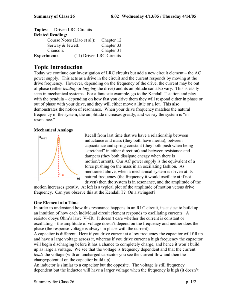
Mechanical Analogs x max
Recall from last time that we have a relationship between inductance and mass (they both have inertia), between capacitance and spring constant (they both push when being
“stretched” in either direction) and between resistance and dampers (they both dissipate energy when there is motion/current). Our AC power supply is the equivalent of a force pushing on the mass in an oscillating fashion. As mentioned above, when a mechanical system is driven at its
ω
0
ω natural frequency (the frequency it would oscillate at if not driven) then the system is in resonance, and the amplitude of the motion increases greatly. At left is a typical plot of the amplitude of motion versus drive frequency. Can you observe this at the Kendall T? On a swingset?
One Element at a Time
In order to understand how this resonance happens in an RLC circuit, its easiest to build up an intuition of how each individual circuit element responds to oscillating currents. A resistor obeys Ohm’s law: V=IR. It doesn’t care whether the current is constant or oscillating – the amplitude of voltage doesn’t depend on the frequency and neither does the phase (the response voltage is always in phase with the current).
A capacitor is different. Here if you drive current at a low frequency the capacitor will fill up and have a large voltage across it, whereas if you drive current a high frequency the capacitor will begin discharging before it has a chance to completely charge, and hence it won’t build up as large a voltage. We see that the voltage is frequency dependent and that the current leads the voltage (with an uncharged capacitor you see the current flow and then the charge/potential on the capacitor build up).
An inductor is similar to a capacitor but the opposite. The voltage is still frequency dependent but the inductor will have a larger voltage when the frequency is high (it doesn’t
Summary for Class 26 p. 1/2
Summary of Class 26 8.02 Wednesday 4/13/05 / Thursday 4/14/05 like change and high frequency means lots of change). Now the current lags the voltage – if you try to drive a current through an inductor with no current in it, the inductor will immediately put up a fight (create an EMF) and then later allow current to flow.
When we put these elements together we will see that at low frequencies the capacitor will
“dominate” (it fills up limiting the current) whereas at high frequencies the inductor will dominate (it fights the rapid changes). At resonance (
ω
= 1 LC ) the frequency is such that these two effects balance and the current will be largest in the circuit. Also at this frequency the current is in phase with the driving voltage (the AC power supply).
Seeing it Mathematically – Phasors
V
0 L
V
0 S
ϕ
It turns out that a nice way of looking at these relationships is thru phasor diagrams. A phasor is just a vector whose magnitude is the amplitude of either the voltage or current through a given circuit element and whose angle corresponds to the phase of that voltage or
V
0 C
I
0
V
0 R current. In thinking about time dependence of a signal, we allow the phasors to rotate about the origin (in a counterclockwise fashion) with time, and only look at their component along the y-axis. This component oscillates, just like the current and voltages in the circuit.
We use phasors because they allow us to add voltages across different circuit elements even though those voltages are not in phase with each other (so you can’t just add them as numbers). For example, the phasor diagram above illustrates the relationship of voltages in a series LRC circuit. The current I is assigned to be at “0 phase” (along the x-axis). The phase of the voltage across the resistor is the same. The voltage across the inductor L leads
(is ahead of I ) and the voltage across the capacitor C lags (is behind I ). If you add up (using vector arithmetic) the voltages across R, L & C (the red and dashed blue & green lines respectively) you must arrive at the voltage across the power supply. This then gives you a rapid way of understanding the phase between the drive (the power supply) and the response
(the current) – here labeled φ .
Important Equations
Impedance of R, L, C: = X
C
=
ω
1
C
(I leads), X
L
= ω L (I lags)
Experiment 11: Driven LRC Circuits
Preparation : Read lab write-up.
This lab consists of two parts. In the first you will see how qualitatively the amplitude and phase of the current in an LRC circuit change as a function of drive frequency. In the second you will plot the amplitude dependence and measure the quality factor (Q) of the circuit.
Summary for Class 26 p. 2/2


