Homework Set 7 22.313J, 2.59J, 10.536J THERMAL-HYDRAULICS IN POWER TECHNOLOGY
advertisement
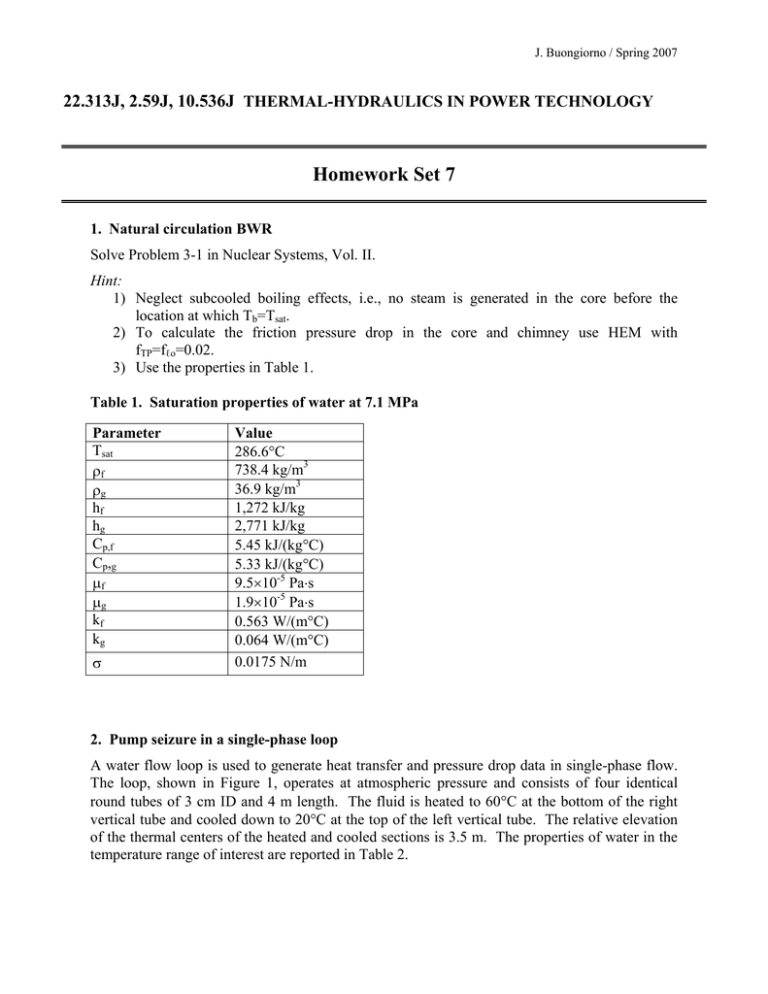
J. Buongiorno / Spring 2007 22.313J, 2.59J, 10.536J THERMAL-HYDRAULICS IN POWER TECHNOLOGY Homework Set 7 1. Natural circulation BWR Solve Problem 3-1 in Nuclear Systems, Vol. II. Hint: 1) Neglect subcooled boiling effects, i.e., no steam is generated in the core before the location at which Tb=Tsat. 2) To calculate the friction pressure drop in the core and chimney use HEM with fTP=fℓo=0.02. 3) Use the properties in Table 1. Table 1. Saturation properties of water at 7.1 MPa Parameter Tsat ρf ρg hf hg Cp,f Cp,g μf μg kf kg σ Value 286.6°C 738.4 kg/m3 36.9 kg/m3 1,272 kJ/kg 2,771 kJ/kg 5.45 kJ/(kg°C) 5.33 kJ/(kg°C) 9.5×10⁻⁵ Pa⋅s 1.9×10⁻⁵ Pa⋅s 0.563 W/(m°C) 0.064 W/(m°C) 0.0175 N/m 2. Pump seizure in a single-phase loop A water flow loop is used to generate heat transfer and pressure drop data in single-phase flow. The loop, shown in Figure 1, operates at atmospheric pressure and consists of four identical round tubes of 3 cm ID and 4 m length. The fluid is heated to 60°C at the bottom of the right vertical tube and cooled down to 20°C at the top of the left vertical tube. The relative elevation of the thermal centers of the heated and cooled sections is 3.5 m. The properties of water in the temperature range of interest are reported in Table 2. J. Buongiorno / Spring 2007 At normal operating conditions, the fluid is circulated by a pump with a characteristic curve described by the following equation: ΔPpump = a (1 − m ) b where ΔPpump is the pump head, m is the mass flow rate, a=1 kPa and b=1.3 kg/s. 4m Q 3.5 m 4m g Q Pump Figure 1. Schematic of the flow loop. i) Calculate the mass flow rate in the loop at steady-state. ii) Now suppose that at t=0 a pump seizure occurs, so that the pump head vanishes instantaneously. Calculate the mass flow rate in the loop for t>0. (Hint: assume that during the transient the control system maintains the same temperatures of the steadystate situation) Assumptions: - Neglect the acceleration terms (Facc) and form terms (Fform) in the momentum equation. To calculate the friction pressure drop (Ffric), use f = 0.316/Re0.25. To calculate the gravity term (Fgrav), use the Boussinesq assumption. Table 2. Water properties in the temperature range of interest. Parameter ρℓ Cpℓ kℓ μℓ β Value 992.2 kg/m3 4.2 kJ/(kg⋅K) 0.63 W/(m⋅K) 6.5×10⁻⁴ Pa⋅s 3.74×10⁻⁴ 1/K J. Buongiorno / Spring 2007 3. Flow distribution in the BWR core The “canned” design of the BWR Fuel Assemblies (FAs) makes it reasonable to model the BWR core as an array of multiple heated channels connected only at the inlet and outlet plena. The total number of FAs is 748, of which it is assumed that 740 operate at the nominal power of 4.0 MW per assembly, and 8 (the hot FAs) at 5.5 MW. You are to analyze the steady-state behavior of this system. In doing this, consider also the effect of coolant bypass, i.e., not all the coolant flows in the FAs; some coolant flows in the gap between the fuel assemblies. Model coolant bypass as an unheated channel connected to the inlet and outlet plena (Figure 2). The geometry of all channels is reported in Table 3. OUTLET PLENUM Hot FAs Nominal FAs 1 2 … 740 1 2 …8 Bypass channel INLET PLENUM Figure 2. The BWR core as an array of parallel channels connected at plena. The boundary conditions for this problem are as follows: • • • Total mass flow rate: 13,000 kg/s Outlet plenum pressure: 7.1 MPa Inlet plenum temperature: 280°C (corresponding to an inlet enthalpy of 1236.8 kJ/kg) Question Write a complete set of equations that would allow you to calculate the mass flow rate in the hot FAs. Write all equations explicitly, i.e., do not just indicate functional dependencies. Make sure to clearly identify all known and unknown parameters. You will receive extra-credit, if you actually solve the equations to provide a numerical value for the mass flow rate in the hot FAs. Assumptions: - Steady-state upflow in all channels. Axially constant heating in the fuel assemblies. Neglect subcooled boiling effects, i.e., no steam is generated in the core before the location at which Tb=Tsat. Use the properties from Table 1 of Problem 1. Neglect the dependence of the properties on temperature and pressure. J. Buongiorno / Spring 2007 - Neglect acceleration and form terms in the momentum equation for the FAs. To calculate the friction pressure drop, use f =0.184/Re0.2 and HEM with fTP=fℓo To calculate the gravity pressure drop, use HEM. Neglect acceleration and friction terms in the momentum equation for the bypass channel. Consider the form term in the momentum equation for the bypass channel. Assume a form coefficient equal to 40. Table 3. Geometry. Number of channels Flow area (m2/channel) Equivalent diameter (cm) Length (m) Nominal FAs 740 0.0091 1.22 3.8 Hot FAs 8 0.0091 1.22 3.8 Bypass channel 1 2.0 1.0 3.8

