Procedure for Estimating Preliminary Design Parameters - Example
advertisement
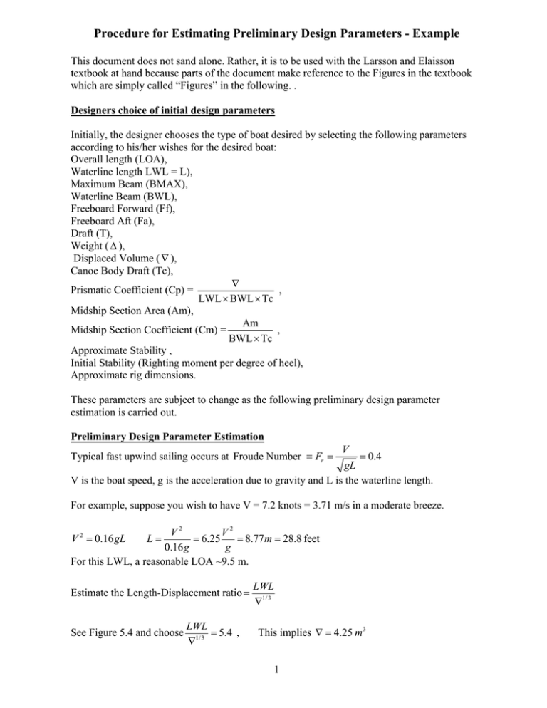
Procedure for Estimating Preliminary Design Parameters - Example This document does not sand alone. Rather, it is to be used with the Larsson and Elaisson textbook at hand because parts of the document make reference to the Figures in the textbook which are simply called “Figures” in the following. . Designers choice of initial design parameters Initially, the designer chooses the type of boat desired by selecting the following parameters according to his/her wishes for the desired boat: Overall length (LOA), Waterline length LWL = L), Maximum Beam (BMAX), Waterline Beam (BWL), Freeboard Forward (Ff), Freeboard Aft (Fa), Draft (T), Weight ( ∆ ), Displaced Volume ( ∇ ), Canoe Body Draft (Tc), ∇ Prismatic Coefficient (Cp) = , LWL × BWL × Tc Midship Section Area (Am), Am Midship Section Coefficient (Cm) = , BWL × Tc Approximate Stability , Initial Stability (Righting moment per degree of heel), Approximate rig dimensions. These parameters are subject to change as the following preliminary design parameter estimation is carried out. Preliminary Design Parameter Estimation V = 0.4 gL V is the boat speed, g is the acceleration due to gravity and L is the waterline length. Typical fast upwind sailing occurs at Froude Number ≡ Fr = For example, suppose you wish to have V = 7.2 knots = 3.71 m/s in a moderate breeze. V2 V2 = 6.25 = 8.77m = 28.8 feet 0.16 g g For this LWL, a reasonable LOA ~9.5 m. V 2 = 0.16 gL L= Estimate the Length-Displacement ratio = See Figure 5.4 and choose LWL = 5.4 , ∇1/ 3 LWL ∇1/ 3 This implies ∇ = 4.25 m3 1 Please note that since the time that the textbook was published, the International Measurement Standard (IMS) rating and handicapping rule for racing boats has favored boats with 15 to 20% less displacement than this indicates. We proceed with the method of the textbook since it leads to sturdier and more comfortable yachts than the IMS Rule. See Figure 5.22. It indicates that the optimum prismatic coefficient (Cp) for this boat ~ 0.6. This applies to the canoe body without appendages. The midship section area (Am) can now be calculated. 0.6 Am × 8.77 = 4.25 See Figure 5.32 LOA ≈ 3.5 BMAX Am = 0.807 m 2 . BMAX ≅ 2.71 m=8.9 Feet Typical rations of BWL/BMAX are 0.78 to 0.82 so we choose BWL = 2.15 m. LWL ≈ 17 Tc=0.515 m Tc × BWL=1.107 m 2 Tc Cm = 0.807/1.107 = 0 0.73 , This value leads to a reasonably shaped midship section. See Figure 5.34 See figure 5.36 Freeboard Forward (Ff)/LWL ~ 0.144, Ff = 11.26 m = 4.14 Feet. See page 94 of Textbook, Ff/Fa ~ 1.2, Fa = 1.052 m = 3.45 feet. See Figure 4.21, Choose a Dellenbaugh angle. This is the the angle that the boat would heel with the sails sheeted in and with a wind pressure on trhe sails of 1q pound/ft2. Traditionally the triangular area of the sails is used where the fore triangle is used for the jib area. For typical jib overlaps and mainsail leech shapes, the actual sail area is about 1.18 times the traditional triangular areas (mainsail triangle + fore triangle). Choose a Dellenbaugh angle for actual sail area that is 1.18 times trhe value you obtain from Figure 4.21. Based on the type of keel you choose, estimate the height of the center of gravity of the boat. Make an approximate waterline planform using the design values of LWN and BWL. Then, using the methods of determining initial stability in the previous reading material, estimate the righting moment per degree of heel for the boat. Assume that this righting moment per degree applies up to the Dellenbaugh angle. This will provide an estimate of the righting moment at the Dellenbaugh angle. Now, design a rig with an area and height such that when a pressure of 1 pound per square foot is applied to the sails, the heeling moment equals the previously computed righting moment. Typical aspect ratios for Mast height/boom length are about 3.0 as are typical ratios of jib height/jib foot. However, the jib aspect ratio can vary from this considerably, depending on the designers choice of fore triangle aspect ratio and amount of jib overlap. This and the desifgners choice of mainsail planform are why it is recommended that Dellenbaugh angle based on actual sail area should be used. At this point, the major preliminary design parameters and approximate preliminary design sail dimensions are known. 2
