3.15 - Problem Set 6 Solutions Problem 1 a. 1.55 µm
advertisement
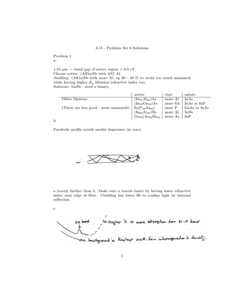
3.15 - Problem Set 6 Solutions Problem 1 a. 1.55 µm → band gap of active region = 0.8 eV. Choose active: (AlGa)Sb with 10% Al cladding: (AlGa)Sb with more Al, eg 20 - 40 % to avoid too much mismatch while having higher Eg Mention refractive index too. Subtrate: GaSb - need a binary. Other Options: (These are less good - more mismatch) active (In75 Al25 )As (In50 Ga50 )As In(P40 As60 ) (In60 Al40 )Sb Ga70 (As50 Sb50 clad. more more more more more Al Ga P Al As substr. InAs InAs or InP GaAs or InAs InSb InP b. Parabolic profile avoids modal dispersion (in core). a travels further than b. Make sure a travels faster by having lower refractive index near edge of fiber. Cladding has lower RI to confine light by internal reflection. c. 1 d. 0.15dB/m = 10 10 log(Pin /Pout ) = log 1000 = 30/L L L So: L = 30/0.15 = 200km. e. σt = σλ LDλ Dλ = 20ps/km · nm, σλ = 2nm, L = 200km ⇒ σt = 8ns Pulses would spread by 8 ns, so max data rate = 2 1 q × 109 /s = 125MHz. Problem 2 a. If the refractive index of the material changes (increases), the light will be de­ layed going through L will be out of phase, so will cancel light from the lower arm. b. To modulate a laser signal prior to sending down fiber. Better than turning the laser on & off. That would give temp. drift ⇒ wavelength dring and wouldn’t be fast enough. c. 1 n = n0 − rn30 � 2 Here n0 = 2, r = 10−12 m/V, 3 How much change in n is required? We want to delay the light by a half wave­ length as it passes through. 1.5 µm light in vacuum → 1.5 n = 0.75µm wavelength in the material. 1 mm length of material contains 10−3 1.5 −6 n ·10 = 1.33 · 103 wavelengths. If we want (1.33 · 103 ) + 12 wavelengths, wew need to change n so that 1 2·10−3 2 + 1.5·10−6 or 103 1.5 n = 1 2 + 4 3 10−3 n 1.5·10−6 = · 103 n = 2.00075 So we need n − n0 = 0.00075. 1 3 rn � = 0.00075 2 0 0.00075 �= × 2/8 = 0.188MV/m 10−10 Over a distance of 10 µm, V = 1.88 volts. d. Materials lacking a center of symmetry (& transparent!) e. LiNbO3 NH4 H2 PO4 KH2 PO4 trigonal 3 m tetragonal 42 m 10 dB/cm ⇒ the light is attenuated by 1 dB since it is 1 mm long. � � dB 10 Pin attenuation = 10 = log cm L Pout 10 log(Pin /Pout ) = 1 Pin /Pout = 1.25 So 25% of the light power is absorbed. This will degrade the performance. Even when the light is out of phase, some will get through since there will be incom­ plete cancellation. 4 Problem 3 a. Diamagnet - µr is slightly less than one. Magnetization of the material weakly opposes the applied field. Paramagnet - µr is slightly greater than one. Magnetization is weakly aligned with applied field. Ferromagnet - spins are aligned by the exchange interaction. µr is very large, on the order of 100-1000’s and non-linear. Material experiences spontaneous magnetization. 5 Antiferromagnet - spins are antiparallel. No net magnetization occurs. Occurs if there is separation between magnetic atoms so exchange energy does not dom­ inate. Ferrimagnet - similar to antiferromagnet but opposing spins do not cancel in the sublattice so there is a net magnetization. b. B and H are the same vector outside the magnet. 6 c. Joule = F · d = kg · m2 s2 d. B-H loop is the same as the M-H loop except for a factor of µ0 and the µ0 H term which is linear. The B-H loop has a slope and shows the magnetic flux density vs. H while the M-H shows the material magnetization vs. H. Coercivity is the applied field required to return a material to a state of zero net magnetization. Remanance is the remaining magnetization when the ap­ plied field is removed from a saturated magnet. Permeability characterizes the material response to an applied magnetic field, µr = 1 + M H. Hysteresis loss is energy used in cycling the B-H loop due to irreversible pro­ cesses such as domain wall motion. Eddy current loss refers to the resistive losses due to the induced eddy currents. 7

