Clinton Campbell EGGN512
Clinton Campbell
EGGN512
Goal: Match drill points to image in
CNC coordinates
Find drill centers
Assume CAM file has no noise
We want white blobs under a certain size
Find the centroids of the blobs
The Platform
1 inch circles with centers spaced at 8 inches
Allows to find object relative to origin
Allows to calculate distance per pixel
The Camera setup
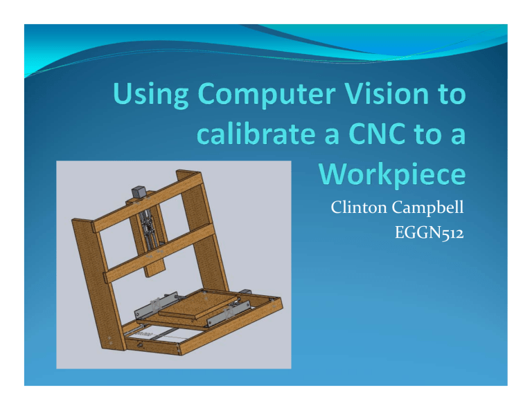
The camera is mounted on the Z axis (it moves with the tool)
3 pictures were taken
1 at the origin at full height
1 at center at full height
1 at center at bottom
Calibration images
First and second image calibrate the conversion factors
Third image finds the origin and calculates the transformation
Matching the Images
Interpretation tree
Match lines by size against other lines, and compare the angle and distance between centers
Match chains of 3
Use a Hough voting pattern for each set of matches
7
2
4
6
8
9
3
5
1
11
10 29
22
7 17
14
8
32
16
18
5
13
38
20
1
34
7
4
22
30
3637
14 2
12
28
6 16
4
19 2
5
17
3
7
9
18
1
11
Found Lines
7
2
1
4
6
3
5
7
4
1 6
2
3
5
Correspondence =
17 11
9 4
13 28
7 6
13 28
7 6
19 13
Angle = 7.13
degrees
True = 6.8
degrees
Translation = (250,267)
True = (238, 267)
Using blobs for more accuracy
Rotate Cam file and close the image and reduce noise
Look for blobs of a certain size, while ignoring the platform markers
1
1
Use the Blob information
The blob centroids and bounding box corner coordinates add information to the translation
Overlaying the images confirms correct matching
Pruning Our Tree
We check that the lines fall within a range of the most common angle
Check that the blob bounding box dimensions match
Check that the translations of lines falls within a range of blob translation
H
Match the Drill Points
cos sin
0
sin cos
0
Tx
Ty
1
Rotate and translate the drill points
Visually Confirm match and send to CNC
Demonstration
Motors Moving
Things That Need Work
Compensating for backlash on lead screws on
CNC
Optimizing traversal of points
Further optimizing of thresholds and line selecting parameters
Using a copper circuit board

