Due: Monday November 10 1.364 ADVANCED GEOTECHNICAL ENGINEERING HOMEWORK NO.3
advertisement
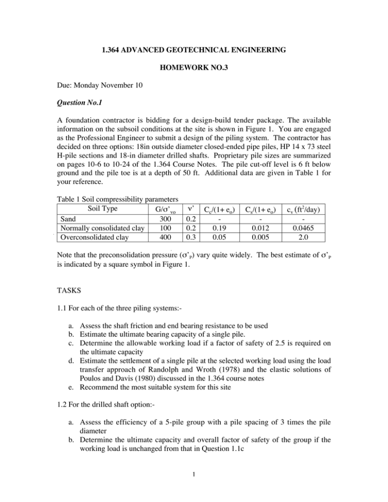
1.364 ADVANCED GEOTECHNICAL ENGINEERING HOMEWORK NO.3 Due: Monday November 10 Question No.1 A foundation contractor is bidding for a design-build tender package. The available information on the subsoil conditions at the site is shown in Figure 1. You are engaged as the Professional Engineer to submit a design of the piling system. The contractor has decided on three options: 18in outside diameter closed-ended pipe piles, HP 14 x 73 steel H-pile sections and 18-in diameter drilled shafts. Proprietary pile sizes are summarized on pages 10-6 to 10-24 of the 1.364 Course Notes. The pile cut-off level is 6 ft below ground and the pile toe is at a depth of 50 ft. Additional data are given in Table 1 for your reference. Table 1 Soil compressibility parameters Soil Type G/s’vo Sand 300 Normally consolidated clay 100 Overconsolidated clay 400 n’ 0.2 0.2 0.3 Cc/(1+ eo) 0.19 0.05 Cs/(1+ eo) 0.012 0.005 cv (ft2/day) 0.0465 2.0 Note that the preconsolidation pressure (s’P) vary quite widely. The best estimate of s’P is indicated by a square symbol in Figure 1. TASKS 1.1 For each of the three piling systems:a. Assess the shaft friction and end bearing resistance to be used b. Estimate the ultimate bearing capacity of a single pile. c. Determine the allowable working load if a factor of safety of 2.5 is required on the ultimate capacity d. Estimate the settlement of a single pile at the selected working load using the load transfer approach of Randolph and Wroth (1978) and the elastic solutions of Poulos and Davis (1980) discussed in the 1.364 course notes e. Recommend the most suitable system for this site 1.2 For the drilled shaft option:a. Assess the efficiency of a 5-pile group with a pile spacing of 3 times the pile diameter b. Determine the ultimate capacity and overall factor of safety of the group if the working load is unchanged from that in Question 1.1c 1 c. Determine the elastic settlement of the pile group using the load transfer method of Randolph and Wroth (1978) and check against that using Poulos and Davis (1980) d. Estimate the additional settlement of the pile group due to long term consolidation of the soft clay (i.e., assuming 90% of primary consolidation has been completed). Question No.2 Due to problems with vibrations caused by conventional pile driving methods, driven piles are becoming more difficult to use on sites in close proximity to sensitive structures. As a consequence, jacked-in piles are slowly finding their market niche in the foundation industry. In order to verify the behavior of a jacked-in pile, a typical pile will be subjected to a static compression load test. The trial pile consists of an open ended steel pipe pile with an outer diameter of 3ft and a thickness of 0.25ins. The pile is installed to a depth of 58.0ft from a piling platform (Ground surface at El. +81.3ft). The soil conditions at the test site are shown in Figure 2. TASKS 2.1 Based on the information available:a. Assess the skin friction and end bearing resistance based on the given SPT and CPT data b. Estimate at what test load the trial pile will fail c. Predict the likely settlement of the pile at one third of the failure load using the methods of Randolph and Wroth (1978) and Poulos and Davis (1980). 2.2 If a six-pile group consisting of 2 rows of 3 piles (all installed to the same toe elevations and a pile spacing of 4 times the pile diameter) were to be tested, a. What will be the expected failure load? b. What is the group efficiency? c. What will be the settlement of the pile group estimated using Randolph and Wroth (1978) and Poulos and Davies (1980)? 2 Water Content, w (%) Vertical Effective Stresses (ksf) 0 10 Sand Fill 0 0 10 20 30 40 50 1 2 3 4 5 Range of s' 6 7 80 SPT Blow Count (blows/ft) 10 20 30 40 50 60 70 v0 s' p 20 Depth (ft) Soft-Medium Clay 30 40 50 70 Stiff Clay 60 U (1960) UU (1988) FV (1988) SPT - N 80 0.0 Note: Water table shown at time of pile installation 0.5 1.0 1.5 Undrained Shear Strength, s u (ksf) Figure 1. Subsoil conditions at project site 3 Point Stress-Qc (Kg/cm2) SPT N (blows/ft) 15 Depth (ft) 20 25 30 35 40 45 50 30 40 1 2 3 4 5 6 31 60 10 15 20 25 36 9 30 10 35 11 12 13 14 15 16 55 500 5 22 7 8 0 Silty Sand 10 20 Clayey Fine Sand 5 10 Fine Sand GL +81.3' Local Friction-LF (Kg/cm2) 6 40 45 50 55 17 18 60 19 65 20 65 (ft) (m) Cone Penetration Test Standard Penetration Test Figure 2. Soil profile and in-situ test data 4


