Lecture 6 - Quantum effects in heterostructures, II - Outline
advertisement
6.772/SMA5111 - Compound Semiconductors
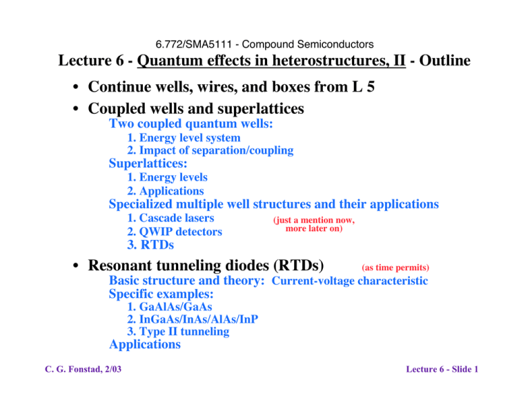
Lecture 6 - Quantum effects in heterostructures, II - Outline
• Continue wells, wires, and boxes from L 5
• Coupled wells and superlattices
Two coupled quantum wells:
1. Energy level system
2. Impact of separation/coupling
Superlattices:
1. Energy levels
2. Applications
Specialized multiple well structures and their applications
1. Cascade lasers
2. QWIP detectors
(just a mention now,
more later on)
3. RTDs
• Resonant tunneling diodes (RTDs)
(as time permits)
Basic structure and theory: Current-voltage characteristic
Specific examples:
1. GaAlAs/GaAs
2. InGaAs/InAs/AlAs/InP
3. Type II tunneling
Applications
C. G. Fonstad, 2/03
Lecture 6 - Slide 1
Quantum heterostructures - coupled quantum wells
Two isolated quantum wells: identical, isolated levels
n=1
n=1
x
Wavefunctions (identical)
x
Two coupled quantum wells: isolated levels split into two
levels for the combined system, slightly shifted from the
original position
n=2
n=1
x
Symetric Wavefunction
Assymetric Wavefunction
x
C. G. Fonstad, 2/03
x
Lecture 6 - Slide 2
Quantum heterostructures - superlattices
Isolated quantum well:
n=1
x
N coupled quantum wells: isolated levels split into N levels for the
combined system, all slightly shifted from the original position
and forming a mini-band of states
Mini-band
(N levels)
C. G. Fonstad, 2/03
x
Lecture 6 - Slide 3
Superlattices and mini-bands
(Image deleted)
See Y.H. Wang, S.S. Li and Pin Ho, "Voltage-tunable dual-mode operation InAlAs/InGaAs
quantum well infrared photodetector for narrow- and broadband detction at 10 um,"
Appl. Phys. Lett. 62 (1993) 621.
C. G. Fonstad, 2/03
Lecture 6 - Slide 4
Quantum heterostructures - applications
Applications:
Laser diode active layers
QWIP structure
Cascade laser structure
Resonant tunneling diodes
C. G. Fonstad, 2/03
(Lectures 19, 20)
(Lecture 22)
(Lecture 20)
(today)
Lecture 6 - Slide 5
Quantum Tunneling through Single Barriers
Transmission probabilities - Ref:
Jaspirit Singh, Semiconductor
Devices - an introduction, Chap. 1
Rectangular barrier
E
Eco
DEc
x
d
T = 4 {4 cosh2 ad + [(a / k) - (k /a ] 2sinh 2 ad}
where k 2 = 2m* (E - E c ) h 2 and a 2 = 2mo [DE c - (E - E c )] h 2
C. G. Fonstad, 2/03
Lecture 6 - Slide 6
Common 1-d potential energy landscapes, cont.
A one-dimensional resonant tunneling barrier:
GaAs
AlGaAs
GaAs
AlGaAs
GaAs
V(x)
DEc
- x B - x W /2
- x W /2
x W /2
x B + xW /2
x
Classically, electrons with 0 < E < DEc can again not pass from one side
to the other, while those with E > DEc do not see the barriers at all.
Quantum mechanically, electrons with 0 < E < DEc with energies that
equal energy levels of the quantum well can pass through the structure unattenuated; while a fraction of those with E > DEc will be
reflected by the steps.
C. G. Fonstad, 2/03
Lecture 6 - Slide 7
Resonant tunneling diodes
Conduction band edge profiles:
Unbiased:
Biased:
A. At resonance
I-V characteristics:
100% transmission
B. Above resonance
no transmission
C. G. Fonstad, 2/03
Lecture 6 - Slide 8
Resonant Tunneling Diode - theoretical i-v
Model for discussion
Unbiased:
Under bias:
E(x)
E(x)
qV ab/2
EF
Ec
qV ab/2
E1
x
qV ab
x
Ideal i-v for structure drawn, EF and Ec < E1:
i
-(E1-Ec) -(E1-EF)
qvab/2
(E1-EF)
C. G. Fonstad, 2/03
(E1-Ec)
Note: Shape sharpens if tunneling through wires or boxes
and/or from and to wells, wires, or boxes
Lecture 6 - Slide 9
Resonant Tunneling Diode - theoretical i-v, cont.
Variations in characteristics:
Ec < EF = E1
i
i
Ec < E1 < EF
-(E1-Ec)
qvab/2
(E1-EF)
-(E1-Ec)
(E1-Ec)
-(E1-EF)
(E1-Ec)
Immediate turn-on
E1 = (EF - E1)/2
i
Initial slope increases
E1 < (EF - E1)/2
-(E1-Ec) =
(E1-EF)
qvab/2
(E1-Ec) =
-(E1-EF)
qvab/2
-(E1-Ec)
(E1-EF)
i
-(E1-EF)
(E1-Ec)
qvab/2
Peak current reduced
High slope, high peak
C. G. Fonstad, 2/03
Lecture 6 - Slide 10
Resonant tunneling diodes - an example
InGaAs/AlAs/InAs on InP:
Tunneling layers
Overall structure
C. G. Fonstad, 2/03
Lecture 6 - Slide 11
RTDs
InGaAs/AlAs/InAs on InP example cont.:
Band edge profile
Materials system
C. G. Fonstad, 2/03
Lecture 6 - Slide 12
RTDs
InGaAs/AlAs/InAs on InP example cont.:
Record results:
Above: Ipeak/Ivalley = 50
Upper right: high current
density with 4 m.l. barrier
Right: three resonances seen
in device with deep well
C. G. Fonstad, 2/03
Lecture 6 - Slide 13
Resonant tunneling diodes - circuit applications
RTD Loaded Digital Inverters:
Schematic
Characteristics
Concept: A III-V digital inverter cell with a low on-state current
for low static power dissipation.
Evaluation: The low on-state current reduces the static power, but
also reduces the switching speed because the charging current
stays low until the RTD again reaches resonance. On balance
the advantages of the circuit do not justify development costs.
C. G. Fonstad, 2/03
Lecture 6 - Slide 14
Resonant tunneling diodes - circuit applications
RTD Static Memory Cell:
Circuit
Characteristics
Concept: A III-V static memory cell with a low device count and
low static power dissipation.
Evaluation: Works and is fast; the difficulty is making RTDs
reproducibly and integrating them with IC process.
C. G. Fonstad, 2/03
Lecture 6 - Slide 15
