Massachusetts Institute of Technology
advertisement
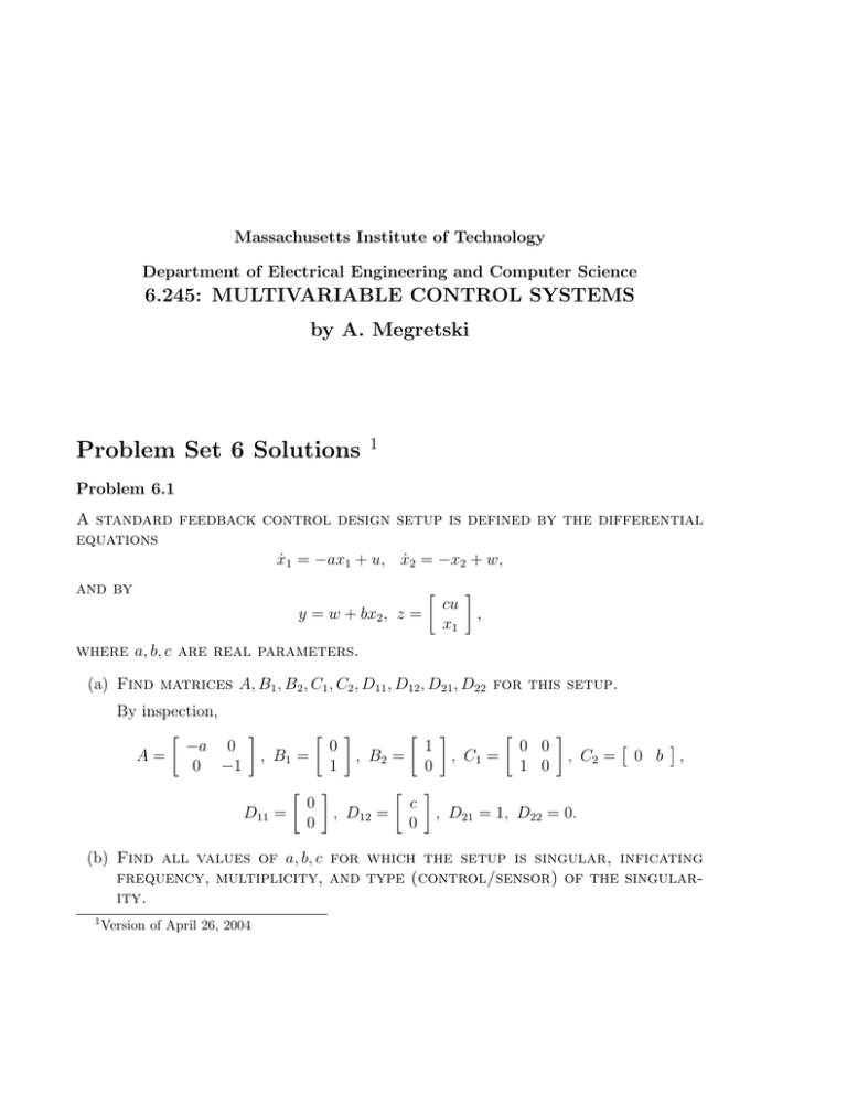
Massachusetts Institute of Technology Department of Electrical Engineering and Computer Science 6.245: MULTIVARIABLE CONTROL SYSTEMS by A. Megretski Problem Set 6 Solutions 1 Problem 6.1 A standard feedback control design setup is defined by the differential equations ẋ1 = −ax1 + u, ẋ2 = −x2 + w, and by y = w + bx2 , z = � cu x1 ⎥ , where a, b, c are real parameters. (a) Find matrices A, B1 , B2 , C1 , C2 , D11 , D12 , D21 , D22 for this setup. By inspection, � ⎥ � ⎥ � ⎥ � ⎥ � � −a 0 0 1 0 0 A= , B1 = , B2 = , C1 = , C2 = 0 b , 0 −1 1 0 1 0 � ⎥ � ⎥ 0 c D11 = , D12 = , D21 = 1, D22 = 0. 0 0 (b) Find all values of a, b, c for which the setup is singular, inficating frequency, multiplicity, and type (control/sensor) of the singular­ ity. 1 Version of April 26, 2004 2 Matrix ⎤ −a − s 0 � 0 −1 −s Mu (s) = � � 0 0 1 0 � 1 0 ⎢ ⎢ c ⎣ 0 is right invertible for all s = j�, � ≤ R. The largest degree of determinant of a 3-by-3 minor of Mu (s) equals d� u = 1 when c = 0, and 2 otherwise. Hence, for c = 0, there is a control singularity at � = →, multiplicity 1 (the difference between system order and d� u ). For c ≥= 0, there are no control singularities. The determinant of ⎤ � −a − s 0 0 −1 − s 1 ⎣ 0 My (s) = � 0 b 1 equals �y (s) = det(My (s)) = (s + a)(s + b + 1). Hence, the system has sensor singularities only when a = 0 or b = −1, in which case the singularity is located at � = 0, and its multiplicity 1 equals the multiplicity of the zero s = 0 of �y (s) (one unless a = b + 1 = 0, which implies multiplicity 2). Problem 6.2 Find H-Infinity and H2 norms of G(s) = Ga (s) as a function of real param­ eter a: (a) G(s) = 1/(s + a) − 2/(s + 2a); The impulse response g = g(t) of G is given by g(t) = e−at − 2e−2at . Since � ⎡ � 0 2 |g(t)| dt = ⎡ � 0 � −2at � 1 − 4e−3at + 4e−4at dt = , e 6a ∞G∞H2 = 1/ 6a. Since s 1 =− , 2 + 3as + 2a 3a + s + 2a2 /s � we have |G(j�)| √ 1/3a, where the equality takes place at � = 2a. Hence ∞G∞� = 1/3a. G(s) = − s2 3 (b) G(s) = (1 − exp(−a2 s))/s. The impulse response g = g(t) of G is given by ⎦ 1, t ≤ [0, a2 ], g(t) = 0, otherwise. Hence ∞G∞H2 = a, and ∞G∞� = a2 . Problem 6.3 Find L2 gains of systems described below (input f , output g, defined for t √ 0). You are not required to prove correctness of your answer. (a) y(t) = e−at f (t). L2 gain equals 1 for a √ 0, and infinity for a < 0. (b) y(t) = f (t)/(1 + a2 f (t)2 ). L2 gain equals 1 for all a. (c) y(t) = f (t + a). L2 gain equals 1 for a � 0, and infinity for a > 0. Problem 6.4 A standard H2 optimization setup is defined by the following transfer functions: � ⎥ � ⎥ 0 1/(s + a) Pwz (s) = , Pwy (s) = 1, Puz (s) = , Puy (s) = −1/(s + a), 0 1 where a ≤ R is a parameter. For all values of a for which the setup is non-singular, find the H2 optimal controller, together with the as­ sociated Hamiltonian matrices, solutions of Riccati equations, and controller/observer gains. A state space model of the setup is given by � ⎥ x ẋ = −ax + u, x(0) = x0 , z = , y = w − x. u The setup is non-singular for a ≥= 0 (when a = 0, there is a sensor singularity at � = 0). 4 The full information abstract H2 optimization has the form ⎡ � Ẋ = −aX + U, (|X |2 + |U |2 )dt � min . 0 The corresponding Hamiltonian matrix is Hf i = � −a 1 1 a ⎥ . The stabilizing solution of the associated Riccati equation is � Pf i = a2 + 1 − a, and the optimal full state feedback gain is given by � Kf i = a − a2 + 1. The state estimation abstract H2 optimization has the form ⎡ � ˙ � = −a� − q, �(0) = �0 , |q |2 dt � min . 0 The corresponding Hamiltonian matrix is Hse = � −a 1 0 a ⎥ . The stabilizing solution of the associated Riccati equation is ⎦ 0, for a > 0, Pse = −2a, for a < 0, and the optimal state estimator gain is given by ⎦ 0, for a > 0, Lse = −2a, for a < 0. For a > 0, the H2 optimal controller has zero transfer function. For a < 0, the H2 optimal controller can be written in the observer-based form � d x − y), u = (a − a2 + 1)ˆ x, xˆ = −aˆ x + u − 2a(−ˆ dt and its transfer function is � 2a(a − a2 + 1) � K(s) = . s + a2 + 1 − 2a 5 Problem 6.5 Open-loop plant P (s) is strictly proper, has a double pole at s = 0, and a zero at s = 0.1. Controller C = C(s) stabilizes the system on Figure 6.1, e f r � C(s) P (s) � − v Figure 6.1: A SISO Feedback Setup and ensures good tracking (transfer function from r to e has gain less than 0.1) for frequencies up to 1 rad/sec. Find a good lower bound on the maximal gain from r to e. Let S denote the closed loop transfer function from r to e. Then, by assumption, S(0.1) = 1. Hence ⎡ � log |S(j�)|d� √ 0. � 2 + 0.12 0 Using the fact that |S(j�)| � 0.1 for � � 1, and |S(j�)| � ∞S∞� for � √ 1, we get ⎡ 10 ⎡ � d� d� √ log 10 , log ∞S∞� 2 2 � +1 10 � + 1 0 i.e. arctan(10) ∞S∞� √ 10 �/2−arctan(10) √ 1014.76 . Problem 6.6 Find the square of the H2 norm of G(s) = s s2 + a 1 s + a 0 as a rational function of real parameters a1 , a0 . A state space model of G is given by � ⎥ � ⎥ � � 0 0 1 A= , B= , C = 0 1 , D = 0. −a0 −a1 1 The solution P of the Lyapunov equation AP + P A� = −BB � 6 has the form P = � 1/2a0 a1 0 1/2a1 0 Hence ∞G∞H2 = � CP C � = � ⎥ . 1 . 2a1
