1.050: Beam Stress-Strength Models (HW#6) Due: October 24, 2007 Fall 2007
advertisement

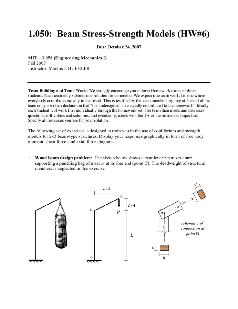
1.050: Beam Stress-Strength Models (HW#6) Due: October 24, 2007 MIT – 1.050 (Engineering Mechanics I) Fall 2007 Instructor: Markus J. BUEHLER Team Building and Team Work: We strongly encourage you to form Homework teams of three students. Each team only submits one solution for correction. We expect true team work, i.e. one where everybody contributes equally to the result. This is testified by the team members signing at the end of the team copy a written declaration that "the undersigned have equally contributed to the homework". Ideally, each student will work first individually through the homework set. The team then meets and discusses questions, difficulties and solutions, and eventually, meets with the TA or the instructor. Important: Specify all resources you use for your solution. The following set of exercises is designed to train you in the use of equilibrium and strength models for 2-D beam-type structures. Display your responses graphically in form of free body moment, shear force, and axial force diagrams. 1. Wood beam design problem: The sketch below shows a cantilever beam structure supporting a punching bag of mass m at its free end (point C). The deadweight of structural members is neglected in this exercise. b L/2 C h L/4 B P B schematic of connection at point B L b A h Due: Wednesday – October 24, 2007 (In class) Page 2 of 5 a) Determine the moment, shear force and axial force along the beam’s axis A-B-C. b) The beam section is a wooden rectangular section of height h and width b (see sketch, right side). The wood is assumed to obey the Tresca strength material law. As a function of the structural dimensions (L), the section dimensions (h, b) and the uniaxial wood strength σ 0 , determine the load-bearing capacity of the structure. In particular, distinguish: i) Pure bending moment capacity. ii) Combined axial force and bending moment capacity. (Neglect the effect of shear forces on the strength capacity). iii) By comparing the load bearing capacity of i) and ii), conclude under which conditions one can neglect the effect of the axial force on the load bearing capacity of this beamtype structure. c) Design Application We consider the following data: L = 2 m, mass of punching bag, m = 130 kg. i) Determine the cross-section parameters h and b? For typical values of wood strength σ 0 , conduct a web search. ii) Design the connection at point B. You have at your disposal steel nails, of strength σ 0,steel = 250 MPa, and 4 mm diameter. Propose a tentative arrangement of the nails at the connection, and estimate the number of nails you need. Sketch a drawing for your proposed design. Assume that the wood can stand the pressure from the nails. (Be creative! You do not need to give the exact minimum number of nails required to prevent failure, but provide a good engineering estimate with its justification). Due: Wednesday – October 24, 2007 (In class) Page 3 of 5 2. Tall building under wind load: We consider a tall building subjected to extreme wind load. The goal of this exercise is to analyze the stress distribution inside the beam at the root of the building and to determine if the building will collapse under the wind load. For our analysis, the following quantities are considered. The building has a square crosssection of side length D = 30 m, height H = 300 m, and an estimated density of ρ b = 1000 kg/m3. The density of air is ρ air = 2 kg/m3, and its kinematic viscosity is ν air = 1.6 × 10 −5 m/s2. In our engineering model, the building is treated as a beam structure, with no variation of forces and stresses in the y − direction. Due: Wednesday – October 24, 2007 (In class) Page 4 of 5 a) Determine the drag force exerted by a hurricane with wind speed of U = 250 km/h. Use the graph below for the analysis. CD 100 10 1 0.1 Re 10-2 100 102 104 106 108 b) Determine the distribution of the section quantities: normal force, shear force, and moment. Assume that the drag force acts as a point force at half of the height of the building (see schematic). Also, consider the deadweight as a distributed load and as a function of height. c) Sketch the solutions for the three section quantities obtained in part b). d) Determine the critical location where the structure is subjected to maximum axial force and bending moment. e) Failure Analysis: You have been hired as a young engineer to asses the following scenario. The given building has collapsed (with no fatalities) due to the passing of the hurricane with wind speed U = 250 km/h. The failure zone corresponded to the critical location determined in part d). Your goal is to determine if the concrete material used to build the tall building complied with the specified strength reported by the construction company. For your analysis consider the following steps: i) Establish the axial force capacity N 0 and bending moment capacity M 0 as functions of the concrete strength σ 0 using the block-stress field approach (see lecture notes). The concrete is assumed to obey the Tresca strength material law (In reality, concrete behaves significantly different under tension or compression load cases. Our assumption to treat it as a Tresca-type material is just a first-order analysis of this Due: Wednesday – October 24, 2007 (In class) Page 5 of 5 challenging problem). ii) Determine the combined bending moment – axial force strength capacity from a linear combination of the pure bending moment capacity and the axial loading capacity (neglect the effect of shear forces on the strength capacity). iii) Determine the effective uniaxial strength of the concrete, σˆ from the derived result from part ii) and the load combination determined in part d). Compare your estimate with the reported strength given by the construction contractor of σ 0 = 17 MPa. f) Mohr Circles and Shear Stresses: For the analysis performed in part e), we restricted ourselves to considering a uniaxial stress field, which at failure takes the form: r r σ = σ̂e x ⊗ e x in the zone of the cross-section subjected to maximum stresses (the parameter σ̂ changes its sign at a point z0 in the cross section; here we only consider the compressive part). In particular, σˆ corresponds to the result obtained in part iii), section e). i) Plot the Mohr circle(s) corresponding to this uniaxial stress field, knowing that σ̂ is a compressive stress in the part considered here. ii) Now, consider the effect of the shear force due to the wind load FD (use your result from part b). Translate this shear force into a shear stress σ xz . Plot the new stress tensor in the Mohr plane: r r r r r r σ = σ̂e x ⊗ e x + σ xz e x ⊗ e z + σ xz e z ⊗ e x Compare your results to part i) of this section and discuss briefly how the consideration of shear stresses would modify the initial analysis using only axial force – bending moment combination.
![Applied Strength of Materials [Opens in New Window]](http://s3.studylib.net/store/data/009007576_1-1087675879e3bc9d4b7f82c1627d321d-300x300.png)
![Strength of Materials [Opens in New Window]](http://s2.studylib.net/store/data/009980952_1-af573ee3f319ca71dbd5b53d99fdf436-300x300.png)


