IV. Transport Phenomena Lecture 20: Warburg Impedance
advertisement

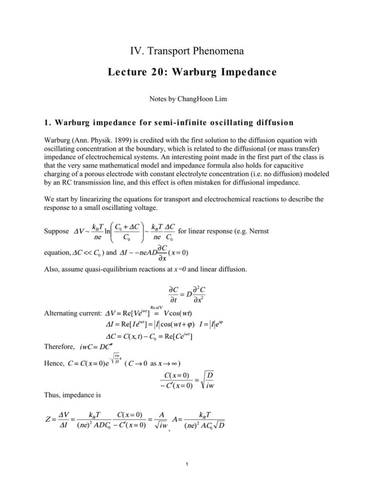
IV. Transport Phenomena Lecture 20: Warburg Impedance Notes by ChangHoon Lim 1. Warburg impedance for semi-infinite oscillating diffusion Warburg (Ann. Physik. 1899) is credited with the first solution to the diffusion equation with oscillating concentration at the boundary, which is related to the diffusional (or mass transfer) impedance of electrochemical systems. An interesting point made in the first part of the class is that the very same mathematical model and impedance formula also holds for capacitive charging of a porous electrode with constant electrolyte concentration (i.e. no diffusion) modeled by an RC transmission line, and this effect is often mistaken for diffusional impedance. We start by linearizing the equations for transport and electrochemical reactions to describe the response to a small oscillating voltage. Suppose equation, for linear response (e.g. Nernst ) and Also, assume quasi-equilibrium reactions at x=0 and linear diffusion. Alternating current: Therefore, Hence, ( as ) Thus, impedance is , 1 Lecture 20: Warburg impedance 10.626 (2011) Bazant This is the same result as an infinite RC transmission line because the mean potential satisfies the same form of linear diffusion equation. 2. Finite Length Warburg Impedance (FLW) for Fuel Cells (also called “open boundary finite-length Warburg” impedance) For oscillating diffusion layer, the characteristic length is C . C C0 00 00 C0 00 00 x 0 x 0 L L Now, C=C0 is imposed on x=L, not at the infinity. At low frequency ( resistor. This situation is depicted in above figure. Solve ), FLW acts like a with C=0 at x=L. The general solution is . B=0 due to C(x=L) =0. Thus, , Hence, the impedance is, , 2 Lecture 20: Warburg impedance 10.626 (2011) Bazant and Then, dimensionless impedance is Hence, this is similar to the following circuit, except in the transition region: Resistor cutoff at low frequency Warburg at high frequency The Nyquist plot is, -Im Re 0 1 This behavior can be clearly seen in impedance spectra for PEM fuel cells, as shown in the next figure. 3 Lecture 20: Warburg impedance 10.626 (2011) Bazant -Z" / Ω cm2 100 50 0 0 50 100 150 200 Z' / Ω cm2 CPE RΩ Rct Ws Image by MIT OpenCourseWare. Figure: (a) Nyquist plots of the impedance of a PEM fuel cell with a Nafion 113 membrane taken at different operating voltages (which leads to different surface concentrations, as explained in previous lectures). The data can be described well by the circuit in (b), where the low-frequency arc on the right comes from a finite-length Warburg impedance with resistance cutoff, given by the formula above. In this case, the double layer capacitance is replaced by a constant-phase element (CPE) attributed to RC transmission line effects, since it is distributed along a porous electrode/membrane interface. 4 Lecture 20: Warburg impedance 10.626 (2011) Bazant 3. FLW Impedance for Li-ion Batteries (also called “blocked boundary finite-length Warburg impedance”) Now apply a zero flux Neuman BC at x=L instead of Dirichlet BC, to represent the finite end of intercalation particle. At higher frequency, this system has the same Warburg impedance as before. However, this system acts as a capacitor at low frequency at this time. Schematic figure is as follows. C C0 x 0 L Still, general solution is With . , A =0. , Use the same notation as before. Then, dimensionless impedance is This is similar to the following circuit except in the transition region 5 Lecture 20: Warburg impedance 10.626 (2011) Bazant The Nyquist plot is, -Im Re 0 1/3 The last figure shows a clear example of the preceding model to describe the diffusion of lithium ions in silicon nanowires, used as anode intercalation material (due to their ability to accommodate the large elastic coherency strain associated with Li intercalation in silicon). The system is well described by a Randles circuit consisting of a parallel RC element for the double layers in series with a finite-length Warburg element for diffusion in the nanowires. By approximating each nanowire as 1D “pseudofilm” for diffusion, the formula above can be used to infer the diffusivity of lithium in silicon, e.g. from the limiting low-frequency resistance (=1/3 dimensionless). Experimental data Fit -10 zim (Ω) -8 0.1 Hz -6 -4 250 Hz -2 20 kHz 0 0 1.0 Hz Surface resistance 2 Diffusion Element 4 10 Hz 6 8 zreal (Ω) 10 12 Image by MIT OpenCourseWare. Figure: Impedance spectrum (Nyquist plot) for a silicon nanowire anode in a Li-ion battery, which is well described by a parallel RC element for the double layer (high frequency “surface resistance”) in series with a finite-length Warburg element with capacitive cutoff (low frequency “diffusion element”). 6 MIT OpenCourseWare http://ocw.mit.edu 10.626 Electrochemical Energy Systems Spring 2014 For information about citing these materials or our Terms of Use, visit: http://ocw.mit.edu/terms.


