I. Equivalent Circuit Models Lecture 6: Impedance of Electrodes
advertisement

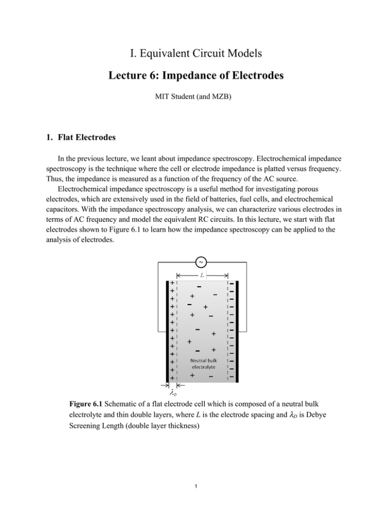
I. Equivalent Circuit Models Lecture 6: Impedance of Electrodes MIT Student (and MZB) 1. Flat Electrodes In the previous lecture, we leant about impedance spectroscopy. Electrochemical impedance spectroscopy is the technique where the cell or electrode impedance is platted versus frequency. Thus, the impedance is measured as a function of the frequency of the AC source. Electrochemical impedance spectroscopy is a useful method for investigating porous electrodes, which are extensively used in the field of batteries, fuel cells, and electrochemical capacitors. With the impedance spectroscopy analysis, we can characterize various electrodes in terms of AC frequency and model the equivalent RC circuits. In this lecture, we start with flat electrodes shown to Figure 6.1 to learn how the impedance spectroscopy can be applied to the analysis of electrodes. Figure 6.1 Schematic of a flat electrode cell which is composed of a neutral bulk electrolyte and thin double layers, where L is the electrode spacing and λD is Debye Screening Length (double layer thickness) 1 Lecture 6: Impedance of electrodes 10.626 (2011) Bazant a. Ideally conducting electrodes In flat electrode cells, if faradaic reactions occur fast and the charge transfer resistance negligible, we can only consider the bulk capacitance and bulk resistance. Under the assumptions, the equivalent RC circuit of the flat electrode cell can be expressed as shown in Figure 6.2. Figure 6.2 Equivalent RC circuit of ideally conducting electrodes or ideally nonpolarizable cell, where Cb is the bulk or geometrical capacitance per area and Rb is the bulk resistance per area. The bulk capacitance per area, Cb, can be calculated by ε/L, where ε is the permittivity of electrolyte and L is the electrolyte spacing. The bulk resistance per area, Rb, can be expressed by L/σb, where σb is the conductivity of electrolyte. In addition, we can set the bulk time scale for charge relaxation as τb, which can be obtained by, Normally, the time scale is a range of MHz. As we leant in the previous lecture, the impedance of the equivalent RC circuit can be expressed by, As a dimensionless form, the impedance can be alternatively expressed by, Where, the dimensionless impedance and the dimensionless frequency corresponding Nyquist plot can be obtained in terms of the dimensionless frequency 6.3. 2 . The as Figure Lecture 6: Impedance of electrodes 10.626 (2011) Bazant Figure 6.3 Nyquist plot of the equivalent circuit for ideally conducting electrodes In the mean time, it is useful information that the linear transformation of the dimensionless impedance should trace out a semicircle. Let’s consider a linear transformation impedance which is expressed by, When we plot the impedance on Nyquist domain, it can be known that the impedance traced out the unit circle, that is , so can be obtained when is translated by +1 and stretched by 1/2 . b. Ideally blocking electrodes If flat electrode cells don’t have faradaic reactions, current leads to capacitive charging of the double layers. Thus, we should consider the double layer capacitance when the equivalent circuit is determined. In other words, it can be deserved that the cell has ideally polarizable electrodes. In this case, the equivalent RC circuit can be drawn as Figure 6.4. Figure 6.4 Equivalent RC circuit for the ideally polarizable electrodes, where CD is the double layer capacitance per area and can be obtained by CD=ε/λD. The double layer charging time scale can be considered as and we can know that the time scale of the double layer charging is much longer than that of the bulk 3 Lecture 6: Impedance of electrodes 10.626 (2011) Bazant charging relaxation due to much thinner double layers than the electrode spacing. As the same way to the ideally conducting electrodes, we can express the impedance and the corresponding dimensionless form as, With the impedance forms, two limits of and can be considered and we can get simplified forms of the dimensionless impedance for the two limits as From the limits, we can easily imagine the corresponding Nyquist plot which has two different regimes shown as Figure 6.5. Figure 6.5 Nyquist plot of ideally blocking electrodes c. Partially polarizable electrodes Until now, we studied about two ideal electrodes of no charge transfer resistance with fast faradaic reactions and no faradaic reactions. Then, in the case of flat electrode cells which have not-fast faradaic reactions, how can we express the RC circuit and Nyquist plot? In this case, we can say the electrodes as partially polarizable electrodes, so the faradaic charge-transfer 4 Lecture 6: Impedance of electrodes 10.626 (2011) Bazant resistance, RF, and double layer capacitance, CD, should be considered, simultaneously. Based on the consideration, the RC circuit can be expressed as shown in Figure 6.6. Figure 6.6 Equivalent RC circuit of partially polarizable electrodes As the same way to the previous ones, the impedance can be expressed by, Depending on the speed of faradaic reactions, we can imagine different forms of Nyquist plot for the equivalent RC circuit. Figure 6.7(a) shows a typical Nyquist plot of partially polarizable electrodes. When faradaic reaction speeds are fast, the Nyquist plot can be as Figure 6.7(b) and it can be considered as blocking electrodes. With the increase of the faradaic reaction speed, the charge transfer resistance decreases and the Nyquist plot become the same to that of ideally conducting electrodes, shown in Figure 6.3, at the limit of RF →0. In contrast, in the case of slow faradaic reactions, the Nyquist plot is shaped as Figure 6.7(c) and we can expect that conducting electrodes show the shape. The slower faradaic reaction speed makes the higher value of the charge transfer resistance and the Nyquist plot eventually has the same to that of ideally blocking electrodes, shown in Figure 6.5, at the limit of RF →∞. 5 Lecture 6: Impedance of electrodes 10.626 (2011) Bazant (a) (b) (c) Figure 6.7 Nyquist plots of cells with partially polarizable electrodes . (a) Balanced bulk and Faradaic resistances, (b) more highly conducting electrodes with relatively large bulk resistance, (c) nearly blocking electrodes with relatively small bulk resistance. 2. Porous Electrodes Porous electrodes have been used for various applications since porous electrodes have many advantages especially for electrochemical systems such as capacitors and batteries. First of all, porous electrodes provide large surface areas which become interfaces between electrodes and electrolytes, resulting in high capacitances and compensating slow electrochemical reactions. In this chapter, we will build up equivalent RC circuits for two types of porous electrodes and study about corresponding Nyquist plots, leading to constant-phase elements (CPEs) with special phase angles ( π / 4 and π / 8 ). We will also discuss an impedance formula that has a constant 6 Lecture 6: Impedance of electrodes 10.626 (2011) Bazant phase element with arbitrary phase angle by employing a self-affine fractal model for a rough electrode surface. These models show that microstructural complexity in rough or porous electrodes can lead to CPE behavior, and we will close by noting that similar behavior can also result for flat electrodes with adsorption or reaction processes possessing a broad distribution of relaxation times. a. Homogeneous microstructure When an electrode is composed of homogeneous micro-porous structures as shown in Figure 6.8(a), we can construct the equivalent RC circuit model with the surface impedance per length, Zs, and the resistance of pore electrolyte per length, Rp, induced by ionic conductions in electrolyte. To simplify the problem, we assume that the electronic conduction in metal is sufficiently fast to neglect the resistance and the assumption is reasonable for normal electrodeelectrolyte cells. In the previous lecture, the homogeneous microstructured electrode which has thin double layers compared to the pore thickness can be expressed by the transmission line model in single microscale as shown in Figure 6.8(b). (a) (b) Figure 6.8 Schematic of homogeneous pore in single microscale (a), the equivalent transmission line model of the homogeneous microstructured porous electrodes with thin electric double layers If we can assume that the transmission line is infinite, the total impedance, Z, can be expressed as Figure 6.9. 7 Lecture 6: Impedance of electrodes 10.626 (2011) Bazant Figure 6.9 Total impedance of the infinite transmission line model can be considered as the same to the recursive model adding a surface impedance per length and a resistance of pore electrolyte per length to the total impedance From the recursive model, the total impedance of Z can be expressed and two limits can be considered as following equation, Where, and (i) Smooth pore walls To determine the surface impedance, we can separately consider the transmission line as two different wall surface conditions. First, let’s consider smooth pore walls which have single length scale pores as shown in Figure 6.8(a). The corresponding transmission line can be composed of capacitances of surfaces per length, Cs, and the resistances of pore electrolyte per length, Rp, as shown in Figure 6.10. Figure 6.10 Equivalent transmission line of the homogeneous microstructures which have smooth pore walls In the transmission line, the surface impedance can be expressed as we can obtain the total impedance and consider two limits as following forms, 8 so that Lecture 6: Impedance of electrodes 10.626 (2011) Bazant The corresponding Naquist plot can be as Figure 6.11 and we can confirm that the impedance curve with respect to frequency is a hyperbola. Figure 6.11 Naquist plot of smooth pore walls If electrodes have a finite length, at very low frequencies, , charging propagates across the entire porous electrode of length L, and the electrode behaves like a pure capacitance, C=CsL. The Nyquist plot of the finite length porous electrode can be shown as Figure 6.12. Figure 6.12 Nyquist plot of finite length porous electrodes (ii) Porous pore walls 9 Lecture 6: Impedance of electrodes 10.626 (2011) Bazant In the previous section, we built the equivalent RC circuit model in smooth pore walls, which have single length scale of pores. Then, let’s suppose the electrode has two different length scales of pores such as that a single large length scale pore has a lot of small scale of pores on the surface as shown in Figure 6.13. Figure 6.13 Schematic of a pore which has porous pore walls In this case, we can consider a simple model letting the surface impedance, Zs, is close to the surface resistance which is much higher than the pore electrolyte resistance. With the assumption, the dimensionless total impedance, , has a close value to and we can model small pores by an array of transmission lines. Finally, we can obtain the dimensionless total impedance as blow, The corresponding Nyquist plot can be obtained as shown in Figure 6.14. Figure 6.14 Nyquist plot of a pore which has porous pore walls 10 Lecture 6: Impedance of electrodes 10.626 (2011) Bazant From the study of the porous electrodes, we can figure out the impedances have a form of , where A and β are constant values, at low frequencies. The impedance form is normally called as a constant phase element. According to the values of β, we can classify the impedance form with four cases. First, β=1/2 is called as Warbug impedance for a simple RC transmission line or diffusion limitations, which will be learnt in the future lecture. Second, 0<β<1 can be due to complex microstructure of the surface or anomalous diffusion or reaction kinetics. When β=0 and β=1, we can consider the impedance form as resistor and capacitor, respectively. b. Fractal rough surfaces A fractal surface is a kind of self affine surfaces and can be a good model to possibly explain the AC response of an interface between a metal and an electrolyte. A simple model of the fractal rough surfaces is the self-affine Cantor block, shown in Figure 6.15. Figure 6.15 A self-affine Cantor block model for the electrolyte surface at the metalelectrolyte interface which has CPE impedance. In each integration, there are N2=4 branches of width smaller by 1/a and length smaller by 1/az, so the surface area of sides is reduced by 1/a2. Theodore Kaplan et al. (1987) showed that the Cantor block model also has a constant element form of impedance: 11 Lecture 6: Impedance of electrodes 10.626 (2011) Bazant c. Distribution of relaxation times It is worth to noting that the constant-phase-angle impedance does not require rough or porous surfaces. It can also arise from anomalous kinetics or transport when there is a broad range of time scales (e.g. due to multistep reactions, or heterogeneous catalysis at many different surface sites), even at an atomically flat surface. In both cases, one can think of the surface or porous material as providing many different circuit pathways for charge storage in parallel, each with a different relaxation time τ = RC . We can model this as a continuous integral over a random distribution of relaxation times, ∞ n(τ )dτ 1 + iωτ 0 Z = R∫ 12 MIT OpenCourseWare http://ocw.mit.edu 10.626 Electrochemical Energy Systems Spring 2014 For information about citing these materials or our Terms of Use, visit: http://ocw.mit.edu/terms.


