16.50 Lecture 8 Types of Nozzles
advertisement
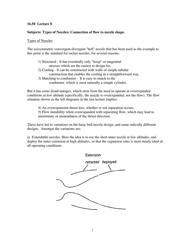
16.50 Lecture 8 Subjects: Types of Nozzles; Connection of flow to nozzle shape. Types of Nozzles The axisymmetric convergent-divergent "bell" nozzle that has been used as the example to this point is the standard for rocket nozzles, for several reasons: 1) Structural - It has essentially only "hoop" or tangential stresses which are the easiest to design for. 2) Cooling - It can be constructed with walls of simple tubular construction that enables the cooling in a straightforward way. 3) Matching to combustor - It is easy to match to the combustor, which is most naturally a simple cylinder. But it has some disadvantages, which stem from the need to operate at overexpanded conditions at low altitude (specifically, the nozzle is overexpanded, not the flow). The flow situation shown as the left diagrams in the last lecture implies: 4) An overexpansion thrust loss, whether or not separation occurs. 5) Flow instability when overexpanded with separating flow, which may lead to uncertainty or unsteadiness of the thrust direction. These have led to variations on the basic bell nozzle design, and some radically different designs. Amongst the variations are: a) Extendable nozzles. Here the idea is to use the short inner nozzle at low altitudes, and deploy the outer extension at high altitudes, so that the expansion ratio is more nearly ideal at all operating conditions. 1 b) The External Expansion nozzle, termed by Rocketdyne the "Aerospike". Schematically, it operates with the flow configuration shown in the top figure at design, with the outer streamtube essentially parallel to the axis and at atmospheric pressure. M0 (Me)design C L M0 Me< (Me)design C L Image by MIT OpenCourseWare. At higher back pressures, that is at lower altitudes than the design value the bounding streamline adjusts by moving inward as shown in the lower figure, and there is no problem with suction, and no separation as encountered in the bell nozzle at high external pressure conditions. In detail, the flow now has a complex structure, with repeated oblique shocks and expansions, but this has little effect on performance. Advantages cited for this type of nozzle are: 1) Better off-design performance 2) Ability to use modular combustors around a nozzle spike, as suggested by the view below, looking upstream at the spike. Disadvantages are: 3) It is difficult to cool the spike. 4) It tends to be heavy, because the structure is not based on simple cylindrical pressure vessels as in the bell nozzle. 2 Note - Such a nozzle was originally planned for the DC-X, but was not used because of weight and development cost. It was included in the Rockwell concept for the X-33, which was abandoned for unrelated structural reasons. Connection of flow to nozzle shape Our channel flow model connects the flow Mach number to the area of the flow passage, but it gives no information as to how the area should vary along the axis. We will now consider another model for the flow, called in its more fully developed form the Method of Characteristics, or MOC. This is our Model 3, that provides a basis for quantifying the connection between the nozzle shape and the flow. For this purpose we will consider the flow to be in two dimensions, supersonic and isentropic. The same procedures can be extended to axisymmetric flow, but the mathematics are somewhat more involved. For references see the following: Kuethe & Chow, pp 219-228 Hill & Petersen, pp 523-530 The expansion of the flow in the supersonic nozzle occurs primarily through weak, isentropic waves. Such a wave in a supersonic flow stands at an angle to the flow, and turns that flow through an angle d as shown in the diagram. Mach wave V a V du V dv d dV sin 1 tan a 1 1 sin 1 tan 1 2 V M M 1 1 M2 1 Associated with this turning is a change in total velocity dV and changes in velocity du and dv in the original direction and perpendicular to it. For d small, dv Vd , du dV From the geometry of the diagram, du tan dv and substituting the above values for du and dv, 3 du dV 1 = = dv Vd! M2 " 1 It follows that we can relate V to θ and M dV d! = V M2 " 1 From the energy equation we can relate V to M. T 1 dT "1 = (! " 1)MdM # = ! " 1 ! T0 1 + T 1 + " 1 M2 M2 2 2 2 V dM dV dT #2 =2 " M = ! RT M V T " !1 2 M dV dM 1 dT dM dM 2 = + = ! " ! 1 V M 2 T M 1+ M2 M 2 dM 1 d# [ ! 1 = ] M 1+ " M2 M2 " 1 2 Rearranging, and counting angles from the sonic point, we have an expression for θ in terms of M (the so-called Prandtl-Meyer function): M M 2 ! 1 dM θ(M) = "1 r !1 2 M 1+ M 2 ! +1 "1 ! " 1 2 "1 2 Tan (M " 1) " Tan M " 1 = ! "1 ! +1 2 This function is tabulated in Kuethe & Chow and Liepmann & Roshko. It is plotted below: 4 There is a maximum angle (equal to 130.5 degrees for γ=1.4, and 208.5 degrees for γ = 1.2). Nozzle Shaping How do we shape a nozzle using this information? Let us assume γ=1.4 so we can use the tables, and suppose we want to design a nozzle for (pc/pe)design = 100. 1) Start with Channel Flow to get the exit Mach number and area ratio. For γ = 1.4, Me is approximately 3.7, and Ae/At is 8.2. Suppose we want a nozzle that produces this Mach number at the exit, and that the flow should be approximately parallel to the axis. The nozzle should therefore look something like: L C M0 Me M1 θ1 Image by MIT OpenCourseWare. For simplicity, let us assume the flow turns around a corner downstream of the throat, where the Mach number is M0 > 1, to an angle θ1, and let us indicate just three of an infinite number of waves making up the "expansion fan". Since the centerline is an axis of symmetry, the waves must reflect from it while canceling the flow deviation, so that the flow downstream of the reflection is axial. When the flow passes through these reflected waves it is deflected toward the axis. If the wall turns to match this deflection where the reflected wave hits it, the wave is just cancelled. The net result is that the flow arrives at the exit with an axial direction and a uniform Mach number. Because of the crossing of waves from two expansion fans, the detailed flow properties at most points need to be computed step-by-step. For a good discussion of this see Liepmann & Roshko. Unfortunately time does not permit it here, except for the uniform region just downstream of the sharp turn, where things are simple. Since the flow is isentropically turned by the corner to the angle θ1, M1 is determined by this angle, from ! (M1 ) " ! (M 0 ) = !1. Also, since the flow is again turned by the second set of waves through the same (but opposite) angle, ! (M e ) " ! (M1 ) = !1. By addition, 2!1 = ! (M e ) " ! (M 0 ) 5 which determines θ1. After this, the Mach number M1 follows directly from either of the above formulas. Of course, if M0=1, θ( M0)=0, and the results simplify further. To get the geometry correct we have to take account of the actual shape of the nozzle throat. More important, this whole argument has been in two dimensions and real rocket nozzles are almost always axisymmetric, but again time does not permit discussing these matters. This sort of calculation results in a nozzle that will produce an axial exit flow of uniform Mach number for a given expansion ratio. The length can be excessive, however, and nonidealities tend to cancel the small thrust contributions of the far downstream sections. Methods have been developed to generate shorter nozzles while accepting some losses due to non-uniformities. The so-called “Rao nozzle” is the nozzle with the optimal contour for a given (less than ideal length). These same ideas can by used to understand the external expansion, or "plug" nozzle. It looks like: M0 Me L C Image by MIT OpenCourseWare. In this case each of the expansion waves from the outer "lip" is cancelled by a turn in the contour of the center body, so that there is just one family of expansion waves. This can be either a two-dimensional nozzle or an axi-symmetric one. It is the basis for the Aerospike nozzle projected for use in the X-33 by Lockheed Martin. It has also been used for aircraft, eg. the F-4, in which the underside of the aft fuselage provides the expansion surface. Such a nozzle is also a key ingredient of the SCRAMJET idea, as exemplified by the X-30 and later implementations. 6 MIT OpenCourseWare http://ocw.mit.edu 16.50 Introduction to Propulsion Systems Spring 2012 For information about citing these materials or our Terms of Use, visit: http://ocw.mit.edu/terms.
