ADDENDUM #1 ITB# 2015-05-001
advertisement
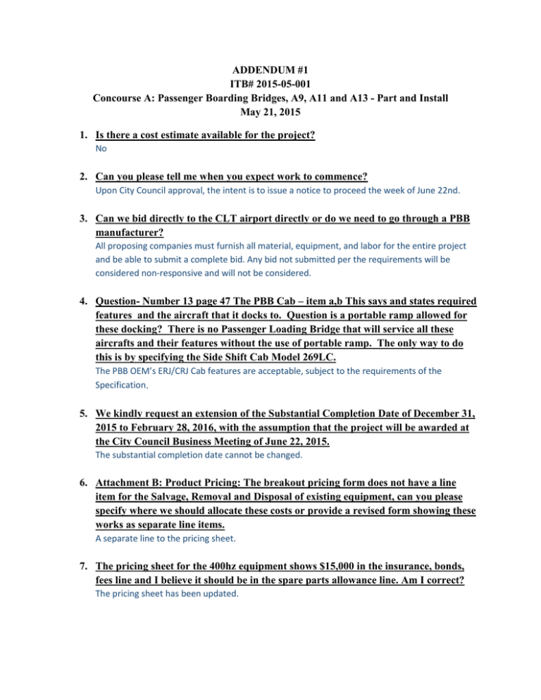
ADDENDUM #1 ITB# 2015-05-001 Concourse A: Passenger Boarding Bridges, A9, A11 and A13 - Part and Install May 21, 2015 1. Is there a cost estimate available for the project? No 2. Can you please tell me when you expect work to commence? Upon City Council approval, the intent is to issue a notice to proceed the week of June 22nd. 3. Can we bid directly to the CLT airport directly or do we need to go through a PBB manufacturer? All proposing companies must furnish all material, equipment, and labor for the entire project and be able to submit a complete bid. Any bid not submitted per the requirements will be considered non-responsive and will not be considered. 4. Question- Number 13 page 47 The PBB Cab – item a,b This says and states required features and the aircraft that it docks to. Question is a portable ramp allowed for these docking? There is no Passenger Loading Bridge that will service all these aircrafts and their features without the use of portable ramp. The only way to do this is by specifying the Side Shift Cab Model 269LC. The PBB OEM’s ERJ/CRJ Cab features are acceptable, subject to the requirements of the Specification. 5. We kindly request an extension of the Substantial Completion Date of December 31, 2015 to February 28, 2016, with the assumption that the project will be awarded at the City Council Business Meeting of June 22, 2015. The substantial completion date cannot be changed. 6. Attachment B: Product Pricing: The breakout pricing form does not have a line item for the Salvage, Removal and Disposal of existing equipment, can you please specify where we should allocate these costs or provide a revised form showing these works as separate line items. A separate line to the pricing sheet. 7. The pricing sheet for the 400hz equipment shows $15,000 in the insurance, bonds, fees line and I believe it should be in the spare parts allowance line. Am I correct? The pricing sheet has been updated. 8. Section 263543 – 400Hz Ground Power Unit and Accessories - The aircraft mix lists ERJ135 and ERJ 145 WHICH ARE 28vdc aircraft. The requirement is for single 90kVA GPUs. Is a 28vdc output required in the GPU to service the ERJ135 AND ERJ145 aircraft? No. The PBB Specification requires a 60 Amp connection on the PBB rotunda for an Owner supplied cart mounted 28Vdc GPU. 9. SECTION 238121 PRECONDITIONED AIR UNIT AND ACCESSORIES Part 2 – Products - 238121: 3.1.A.1. Requires vibration isolation shall be provided so that the PCAir units shall not transmit vibration to the passenger bridges. The rotating assemblies used in the JBT PCA unit are balanced eliminating the need for vibration isolation mounts. Please allow our standard rigid mounting. If PCAir unit produces vibrations, you are required to ensure that the vibration is not transmitted to the PBB. 10. Section 347713 Passenger Boarding Bridges - 347713: 2.7.I.6.c.4: Specifies 2’5” service door clear opening. JBT standard is 2’ 3”. Please allow. At 347713-48, paragraph 2.7.I.6.c.4 has been replaced with the following: “(4) be a minimum of 2’-6” wide, 2’-3” clear, and 6’-7” high.” 11. 347713: 2.7.J.4.b: This section specifies ½” thick wall panels. JBT standard wall panel thickness is 3/8”. Please allow. Comply with the Specification. 12. 347713: 3.3.A.1: This section states the existing GPU’s are to be removed and turned over to the owner. Section 263543 item 1.1.B states the GPU units are to be scrapped. Please clarify. At 263543-1, paragraph 1.1.B, has been replaced with the following: “B. The Contractor shall remove and turn over to the Owner the two (2) existing 400Hz Ground Power Units (GPU), their accessories and doglegs from Gates A9 and A11, as indicated in the Project Specifications.” 13. 347713: 2.4.E.9.f.: The safety cables must have enough clearance above the roof and tie off points to allow ease of attachment of the lanyard clip. Due to tunnel clearances on the A and B tunnels, raising the cables from design is not possible. We can raise the cable on the C tunnel. Please allow our standard design for the A and B tunnels. Comply with the specification. 14. 347713: 2.4.G.10: The PBB shall have an interior security camera system that shall connect to the Owner’s security system at a junction box mounted at the terminal face. Where are the security cameras to be located? As indicated in the Specification, the PBB manufacture shall recommend locations for security cameras and camera type to provide views identified in the Specification. 15. 347713: 2.7.A.2.c.7: Fixtures shall be oriented perpendicular to the center line of the tunnel. Our standard light fixture is 2’ X 4’ troffer recessed fixture. The orientation of the tunnel light fixtures is parallel with the tunnel, not perpendicular. Please accept our standard parallel orientation for the light fixtures in the tunnels. In the bubble and rotunda the light fixture orientation is perpendicular to the tunnel. Comply with the Specification 16. 347713: 2.7.A.2.c.8: Fixture shall have black trim. Our standard trim color for the lighting fixtures is white. Please accept our standard white trim. Comply with the Specification 17. 347713: 2.7.A.2.c.13: Interior Cab Bubble lights and / or any light over the Operator Console, shall be switched on / off from the HMI screen. The light in the bubble is connected to the switched tunnel lighting circuit. It is best to leave this light on that circuit. It is possible that the tunnel lights are on and the bubble light is not. The console area is dark until the operator is at the console to turn on the bubble light. We do not recommend this arrangement of the light circuit. We can have the console flood light switched in the manor. Please remove the bubble light requirement from this section. Comply with the Specification 18. 347713: 2.7.A.2.d.2.iii & iv - iii) Shall be controlled with the Tunnel light switch and shall be on when the Tunnel lights are on. iv) Shall also be controlled by a button on the HMI so the PBB operator can turn the light off/on when docking to the aircraft. Our standard connection for the cab floor floodlight a HMI switch in the console, it is not connected to the tunnel lights. Please accept our standard switching logic. Comply with the Specification 19. 347713: 2.7.A.2.e.1 (1) The PBB and Fixed Walkway will NOT be on a terminal building emergency power circuit so the PBB lighting circuit shall have an in-line battery backup system. Our lighting system now has an emergency battery packs for an LED fixture. This new technology removes the requirement for an in line backup system (UPS) for emergency lighting. Please allow our LED emergency battery packs. Comply with the Specification 20. 347713: 2.7.A.2.k: Quick Disconnect fittings must be MS standard receptacles and plugs and shall be UL or ETL approved. Our standard quick disconnect for motor circuit connections is not a mil spec component. This product is rated at 35 amps, 600 volt operations. Suppliers for this fitting are by Contact Electronics, Weiland, Weidmuller, T&B, or Harting, this configuration has been used on our product at least 15 years. Is this acceptable? These products are UL rated. Submit product information for review during project submittal process. 21. 347713: 2.7.A.3.k.: To prevent the PBB operator from accidentally turning off and disabling the auto level system, the auto-level fault condition and all related audible alarms and warning messages shall be activated whenever the selector switch is moved from “AUTO” directly to the “OFF” position. Our standard key switch is functional positions are “Off – Operate – Auto”. To reset from an auto level warning condition the operator needs to turn the key from auto to operate and then returning it back to auto. Please allow our standard key switch configuration. The purpose of this requirement is not to reset the auto level alarm, but to prevent the Auto Level alarm from accidentally being turned off. Comply with Specification. 22. 347713: 2.7.A.3.o.3, I & ii: If a horizontal travel E-STOP is pressed i) ONLY horizontal travel shall be disabled ii) A large, flashing error message shall be displayed on the HMI identifying a “RAMP E-STOP PRESSED” condition. By definition an E-Stop is an emergency stop. It is not just for one function as described here. Depressing any E-Stop buttons will disable the PBB. We cannot comply with this section. Please remove this from the specification or allow a deviation. Comply with the Specification 23. 347713: 2.7.B.4: The Operator Control Station shall be housed in a NEMA-rated enclosure. Our console assembly is a manufactured assembly, not a purchased enclosure. We comply to the requirements for a NEMA 1 rating. This comprises protection against: incidental contact with the enclosed equipment and Falling dirt. We do not have a certified NEMA rating for this enclosure. Please remove the NEMA reference to the operator console. This assembly is on every unit we manufacture, adding the NEMA certification will increase cost, is our standard acceptable? If the enclosure is NEMA 1 rated, then it would be acceptable. 24. 347713: 2.7.B.13.a.2: 10.2” or greater; Our monitor for this application only comes in 10.1”. Please accept this monitor size. At 347713-33, paragraph 2.7.B.13.a.(2) has been replaced with the following: “(2) 10” or greater.” 25. 347713: 2.7.B.14: PBB Interior Security Camera System; This appears to be an independent system from the cameras needed in section 2.7.B.13 PBB Operator Camera System. Since this is a Cat6 POE system, we will require am IP type camera. Does the cameras need to be adjustable (pan, tilt, zoom)? Can we get the manufacturer name of the customer camera system they will specify so we can look into their product line for submittal purposes? The views that the Owner is requesting are specified. The PBB manufacturer shall propose the appropriate camera positions, number of cameras and type of cameras in order to provide the monitoring required by the Owner. 26. 347713: 2.7.B.16.e, f, g, h e. A push button to ring the Travel Alarm Bell (1) Shall be operational while the PBB is in “OPERATE” or “AUTO” mode. f. Push buttons to extend and retract the canopy. (1) One each for the left and right side of the canopy. Each side of the canopy shall be able to be extended or retracted independently. g. ACF Floor Auto / Manual button h. ACF Floor Operate button These operations are a standard HMI soft button controlled operations. With the 15 inch HMI, the amount of room to place operator buttons is limited. Please allow these operations to be controlled through the HMI. Comply with the Specification 27. 347713: 2.7.B.17.d.2.iii: Ramp E-STOP Warning, different from Console E-STOP message – minimum 1”x 3”; This message will be incorporated with the E-Stop warning message. We will supply E-Stops that disable the PBB. Separate messages are required to distinguish between an E-Stop activated from the Operator Console vs an E-Stop activated from the ramp. Comply with the Specification. 28. 347713: 2.7.B.19: A required layout of the Operator Console face plate and the various controls and indicators is included in APPENDIX I of this Specification. The drawings depicted in appendix I does not take into account the structural frame work of the console enclosure and the mounting hardware for the HMI. We cannot place the buttons that close to the edge (left side). One option is to reduce the size of the HMI. Is that acceptable? Some of the non-motion enable operator that use the HMI soft buttons is the best method. Comply with the Specification 29. 347713: 2.7.B.16.d: The safety hoop shall utilize contact pressure type pads / switches that shall run the full perimeter or circumference of the wheel guard system.;The usage of pressure switches is not recommended. We propose using sensors to detect any obstruction which will stop the horizontal drive. Please accept our proposal. Comply with the Specification. 30. 347713: 2.7.E.7.d; a stainless steel bottom dome sections that the curtains ride on when rolling-up or unrolling from the barrel standard? The Specification says “d. a stainless steel bottom dome sections that the curtains ride on when rolling-up or un-rolling from the barrel” 31. 347713: 2.7.E.9.c: All attachment brackets and hardware shall be SST. Please allow the use of A36 steel material for any welded attachment brackets. This will reduce and issues with dissimilar metal welding. We will comply to SST bolt on brackets. Comply with the Specification 32. 347713: 2.7.H.2.e: Idler chain sprockets shall have a grease fitting to lubricate the bearing and shaft.; Our sprocket uses sealed bearing and is not designed for a grease fitting. Bolts are used as the shaft of the sprockets, there is no channel for the grease to travel in. please remove this section, it is not required. At 347713-45, paragraph 2.7.H.2.e has been replaced with the following: “e. If the Idler chain sprocket bearings are not sealed, the sprocket bearings shall have a grease fitting to lubricate the bearing and shaft.” 33. 347713: 2.7.H.17.b. All attachment hardware, brackets and fasteners shall be SST. Please allow the use of A36 steel material for any welded attachment brackets. This will reduce and issues with dissimilar metal welding. We will comply to SST bolt on brackets. Comply with the Specification 34. 347713: 2.7.I.7.a. - have a one piece galvanized modesty plate installed under the platform Deckspan / Gripstrut or the apron side of the landing frame.; We will provide a modesty shield, but our design is not a one piece assembly. Due to structural elements this assembly is designed in sections. Please allow a sectional modesty shield. Comply with the Specification 35. 347713: 2.7.J.6.d.(3) - ¼ in (6.4mm) thick black ribbed rubber floor covering. Our standard is 3/16 thick material for the ribbed rubber. Please allow our standard. At 347713—52, paragraph 2.7.J.6.d.(3) has been replaced with the following: “(3) minimum 3/8 in. thick black ribbed rubber floor covering.” 36. 347713: 2.7.J.6.e - Cab Exterior - Metal subfloor with ¼ in (6.4mm) thick black ribbed rubber floor covering.; Our standard is 3/16 thick material for the ribbed rubber. Please allow our standard. At 347713-53, paragraph 2.7.J.6.e has been replaced with the following: “e. Cab Exterior - Metal subfloor with minimum 3/8 in. thick black ribbed rubber floor covering” SECTION 238121 PRECONDITIONED AIR UNIT AND ACCESSORIES Part 2 – Products 37. 238121: 2.2.A.4. J&B Aviation Services, and Ameribridge Services are approved for hose baskets. Please allow JBT AeroTech hose basket design. A basket can be supplied by JBT AeroTech as long as it meets all of the specification requirements for the hose basket. 38. 238121: 2.4.B.11.a. In cooling mode the temperature of the preconditioned air at the aircraft shall not exceed 40° F, when the unit is operating normally and not in hot gas bypass or other defrost cycle. Please allow the temperature to be measured at the outlet of the PCA unit. The performance of the insulated duct is not within the control of the PCA unit manufacturer. The JBT AeroTEch PCA unit is rated at 34° F - 38° F at the outlet of the unit. Comply with the Specification. The hose required by the Owner is known and specified so the PCAir unit should be designed to work with the hose. 39. 238121: 2.4.B.17.c. The spec requires the PCA unit control system to have a PBB Pre-cool / Pre-Heat timer that is adjustable from the unit’s controller, that shall be set to 90 minutes, but be adjustable from 30 minutes to 120 minutes. The JBT PCA unit is provided with a timer that is adjustable on the PLC visualization page. It can be changed by using a laptop and PLC software. Will this be acceptable? If laptop and software are supplied with the Project, then this would be acceptable. If not, comply with the Specification. 40. 238121: 2.4.B.23. The PCA unit shall have a DOA approved smoke detector. The JBT PCAir unit uses an Air Products and Controls model number SL2000-N smoked detector. Please approve this smoke detector for use in the PCA unit. 238121: 2.4.B.23 says “23. The PCAir unit shall have an Owner approved smoke detector installed downstream of the electric strip heater”. Submit smoke detector information during design submittal review and approval process for the Owner’s approval. 41. 238121: 2.4.C.1.a. Exterior casing surfaces shall have a baked enamel finish coat after assembly. Please allow our standard powder coated finish. Comply with Specification 42. 238121: 2.4.C.3.a.1. All panels and doors that must be opened to access the interior of the PCA unit for any maintenance or adjustments shall be hinged, lockable, and equipped with hold open mechanism. The JBT unit is provided with hinged doors and bolt on removable panels for maintenance access. The removable panels do not have hinges or hold open devices. Please allow our standard panel design. Comply with Specification 43. 238121: 2.4.E.1.f. Compressor service valves are required. The manufacturer of the compressor used in the JBT 60 ton PCA unit does not offer the compressor with service valve/Rotolock connections. It is only available with solder connections. Please allow our standard compressor and piping system. Comply with the Specification 44. 238121: 2.4.L.15.e. Wire splices of any type shall not be used. We use a fully insulated ¼-inch male and female quick disconnect on the heater temp switches that are provided with wire connections. This is a low voltage connection and the connector is UL listed. Please allow this type of connection. Comply with the Specification 45. With respect to 2.4.L.17., the main power on the JBT PCA unit enters the unit through a circuit breaker enclosure. Is this considered to be the Main Power/Control Panel? Please clarify what is considered to be the Main Power/Control Panel enclosure. No, this is a disconnect; Comply with the Specification. 46. 238121: 2.3.M.2.c. The temperature probe mounting box shall be SST NEMA 3R or 4 rated. The enclosure cover shall be hinged. We cannot find a hinged box in the small size required for the temperature probe. Please provide a source for a small hinged enclosure or allow a standard enclosure that is not hinged to be used in this location. Comply with the Specification 47. 238121: 2.5.B.6. Metal mounting straps, minimum 2 in. wide for aircraft and PBB pre-cool spiral wire wound hose. We use 1-inch wide straps to support the bridge cool spiral wire wound hose. Please allow our standard. Comply with Specification 48. 238121: 2.5.E.5. Main aircraft supply hose storage area shall not exceed 24 in. interior width. Please allow the JBT standard hose basket design with a 45-inch interior width. Comply with Specification 49. 238121: 2.5.E.6. the detachable hose cart shall be a maximum of 24 in interior width. Please allow the JBT standard detachable hose cart design that has a 32-inch interior width. Comply with Specification 238121.1.8 Warranty 50. C.3. Please clarify the “Hand Held Controller” in which the Owner requires an additional 5 Year Warranty. The Controller is the device that is used to input commands and parameters for the PCAir unit. It may or may not be hand held. 238121. 2.2 Manufacturers 51. A.2. May Twist Inc. be added as an approved manufacturer of flexible and spiral wound ductwork/hose? Twist has been manufacturing hoses and ducting for over 5 years. No. Comply with the Specification 52. A.4. May Twist Inc. be added as an approved manufacturer of preconditioned air hose baskets? Our basket design meets or exceeds the criteria for hose baskets within this specification. If the Twist Inc. hose basket meets all of the Specification requirements, then it would be acceptable. But, it must meet the Specification requirements. 238121.2.4 Direct Expansion Preconditioned Air Units 53. B.3. Specification calls for nominal 60 Ton PCA Unit. Based on the aircraft mix and the required Design Conditions, we believe our 45 Ton will adequately cool stated aircraft. Please accept our 45 Ton design. Nominal 60 Ton unit is required. 54. B.23. Specification requires an indication light for the smoke detector. When our unit’s smoke detector activates, the MAINTENANCE REQUIRED light on the pendant control box illuminates. Is this deviation acceptable? Comply with the Specification. 55. C.3. All access panels on the units are completely removable via ¼ turn latches. Is this acceptable in lieu of hinged doors? Comply with the Specification. 56. E.1.i. Specification requires flexible in the suction and discharge line connections. Our compressors and components are rigid mount and therefore do not require flexible joints. Is this acceptable? Comply with the Specification. 57. E.3.b. Our filter drier is directly connected to the refrigeration circuit and is not removable via a bolted access plate, nor does it contain isolation valves as specified. Is this deviation to the specification acceptable? Comply with the Specification. 58. E.8.c. Our gauge port caps are not secured via a chain or plastic strap. Is this deviation acceptable? Comply with the Specification. 59. I.1.a. Our electric heat banks only have three steps of electric resistance. We can add the SCR Heat Control if necessary, but it is a costly option. May our 3 stages of heat be acceptable? Comply with the Specification. 60. L.7 Our wiring connections terminate at the equipment terminal blocks instead of MS standard receptacles and plugs. Is this acceptable? Comply with the Specification. 61. L.15.i. All wiring in our PCA electrical cabinet and pendant control box are permanently identified via color coded wires. May our standard wiring method be considered by the Owner as acceptable? Comply with the Specification. 62. M.1.f.4. Our STOP/RESET button on the pendant control box also serves the purpose of an E-Stop button. May our standard pendant control stop button be considered acceptable? Comply with the Specification. 63. M.2.f. Our standard temperature probe does not contain a light for indicating the temperature probe has failed. Also our standard design consist of a stainless steel wall plate in lieu of a stainless steel mounting box. May our standard be accepted? Comply with the Specification. 2.5 PCAir Accessories 64. E.7. Our main hose basket does not have a hinged, drop down front door. May our standard be acceptable? Comply with the Specifications.
![Purchase Request Form [L02]](http://s3.studylib.net/store/data/008565490_1-0019a09aa88e76e75b2b5be9eeb9fadb-300x300.png)
