Research Journal of Applied Sciences, Engineering and Technology 6(1): 98-101,... ISSN: 2040-7459; e-ISSN: 2040-7467
advertisement
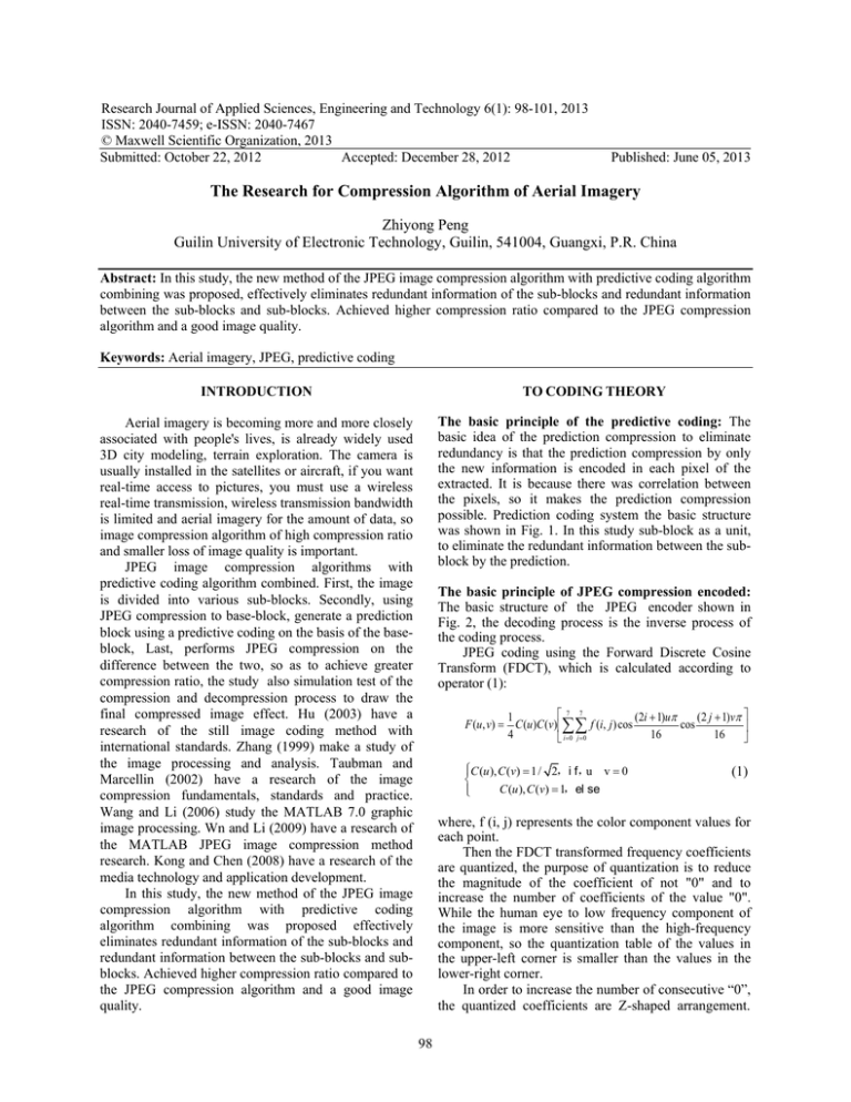
Research Journal of Applied Sciences, Engineering and Technology 6(1): 98-101, 2013 ISSN: 2040-7459; e-ISSN: 2040-7467 © Maxwell Scientific Organization, 2013 Submitted: October 22, 2012 Accepted: December 28, 2012 Published: June 05, 2013 The Research for Compression Algorithm of Aerial Imagery Zhiyong Peng Guilin University of Electronic Technology, Guilin, 541004, Guangxi, P.R. China Abstract: In this study, the new method of the JPEG image compression algorithm with predictive coding algorithm combining was proposed, effectively eliminates redundant information of the sub-blocks and redundant information between the sub-blocks and sub-blocks. Achieved higher compression ratio compared to the JPEG compression algorithm and a good image quality. Keywords: Aerial imagery, JPEG, predictive coding INTRODUCTION TO CODING THEORY Aerial imagery is becoming more and more closely associated with people's lives, is already widely used 3D city modeling, terrain exploration. The camera is usually installed in the satellites or aircraft, if you want real-time access to pictures, you must use a wireless real-time transmission, wireless transmission bandwidth is limited and aerial imagery for the amount of data, so image compression algorithm of high compression ratio and smaller loss of image quality is important. JPEG image compression algorithms with predictive coding algorithm combined. First, the image is divided into various sub-blocks. Secondly, using JPEG compression to base-block, generate a prediction block using a predictive coding on the basis of the baseblock, Last, performs JPEG compression on the difference between the two, so as to achieve greater compression ratio, the study also simulation test of the compression and decompression process to draw the final compressed image effect. Hu (2003) have a research of the still image coding method with international standards. Zhang (1999) make a study of the image processing and analysis. Taubman and Marcellin (2002) have a research of the image compression fundamentals, standards and practice. Wang and Li (2006) study the MATLAB 7.0 graphic image processing. Wn and Li (2009) have a research of the MATLAB JPEG image compression method research. Kong and Chen (2008) have a research of the media technology and application development. In this study, the new method of the JPEG image compression algorithm with predictive coding algorithm combining was proposed effectively eliminates redundant information of the sub-blocks and redundant information between the sub-blocks and subblocks. Achieved higher compression ratio compared to the JPEG compression algorithm and a good image quality. The basic principle of the predictive coding: The basic idea of the prediction compression to eliminate redundancy is that the prediction compression by only the new information is encoded in each pixel of the extracted. It is because there was correlation between the pixels, so it makes the prediction compression possible. Prediction coding system the basic structure was shown in Fig. 1. In this study sub-block as a unit, to eliminate the redundant information between the subblock by the prediction. The basic principle of JPEG compression encoded: The basic structure of the JPEG encoder shown in Fig. 2, the decoding process is the inverse process of the coding process. JPEG coding using the Forward Discrete Cosine Transform (FDCT), which is calculated according to operator (1): 7 7 1 (2i + 1)uπ (2 j + 1)vπ F (u, v) = C (u )C (v) ∑∑ f (i, j ) cos cos 4 16 16 i =0 j =0 C (u ), C (v) 1/= = 2,i f,u v 0 C (u ), C (v) = 1,el se (1) where, f (i, j) represents the color component values for each point. Then the FDCT transformed frequency coefficients are quantized, the purpose of quantization is to reduce the magnitude of the coefficient of not "0" and to increase the number of coefficients of the value "0". While the human eye to low frequency component of the image is more sensitive than the high-frequency component, so the quantization table of the values in the upper-left corner is smaller than the values in the lower-right corner. In order to increase the number of consecutive “0”, the quantized coefficients are Z-shaped arrangement. 98 Res. J. Appl. Sci. Eng. Technol., 6(1): 98-101, 2013 The original signal ∑ xm + em em′ Quantizer − Encoder Table 2: The quantization table of the color difference signals 16 11 10 16 24 40 51 12 12 14 19 26 58 60 14 13 16 24 40 57 69 14 17 22 29 51 87 80 18 22 37 56 68 109 103 24 35 55 64 81 104 113 49 64 78 87 103 121 120 72 92 95 98 112 100 103 Export + xˆm Predictor xm′ ∑ + • • • • Fig. 1: A configuration diagram of the predict coding system subblock DCT Quantizer Entropy encoder The composite data stream • The RGB image is converted to a YUV image The image is divided into sub-blocks Base-block compressed using the JPEG algorithm Generate prediction block using a predictive coding on the basis of the base-block Generating bidirectional prediction block Step 1: Because the human eye is more sensitive to light signals than the color difference signals, in this study first conversion RGB images into a YUV images and then quantizes the light signals and the color difference signals using two different quantization tables. The formula of RGB image is converted to a YUV image is: Quantization table Fig. 2: JPEG encoder flow chart Y = 0.299 R + 0.587G + 0.114 B U= −0.147 R − 0.289G + 0.436 B + 128 V= 0.615 R − 0.515G − 0.1B + 128 99 99 99 99 99 99 99 99 (2) Step 2: The image is divided into 8*8 sub-blocks and three types of sub-block are defined: base-block (I), the Prediction block (P) and Bidirectional prediction block (B). Beginning of the line as defined in the first sub-block as a base-block, the base-block appears interval is N. N subblocks of between base-blocks are the prediction block or bidirectional prediction block. M bidirectional prediction blocks are between base-block with the prediction block or prediction block with prediction block. The subblocks arranged in the basic structure shown in Fig. 3. Step 3: Base-block (I) is compressed using standard JPEG compression algorithm. This study using different quantization table to quantize the frequency coefficients of the light signals or the color difference signals. The quantization table of the light signals is Table 1. The quantization table of the color difference signals is Table 2. Step 4: The generation of the prediction sub-block: The first sub-blocks are transformed using FDCT and then the use Table 1 and 2 quantize respectively the light signals or the color difference signals, the result of quantization with previous quantization result of base-block or prediction block differencing operator by the formula (3). Then the difference result of the Z- Fig. 3: A structure diagram of the sub-block Table 1: The quantization table of the light signals 17 18 24 47 99 99 18 21 26 66 99 99 24 26 56 99 99 99 47 66 99 99 99 99 99 99 99 99 99 99 99 99 99 99 99 99 99 99 99 99 99 99 99 99 99 99 99 99 61 55 56 62 77 92 101 99 99 99 99 99 99 99 99 99 Therefore, in the Run Length Encoding (RLE), there are a lot of continuous “0”. DC coefficients are compressed by Differential Pulse Code Modulation (DPCM) technology; AC coefficients are compressed using the Run Length Encoding (RLE). Then further compression of the results after the DPCM and RLE using entropy encoding. Finally, the tag code and encoded image data comprising the bit data stream. This study in the principle of compression algorithm: The basic idea of this algorithm is the JPEG compression algorithm and the predictive coding algorithm is combined to achieve the purpose of high compression ratio. The coding algorithm steps: 99 Res. J. Appl. Sci. Eng. Technol., 6(1): 98-101, 2013 = DeltaB (i, j ) DI (i, j ) K −1 + DI (i, j ) K +1 − D(i, j ) (4) 2 where, D I (i, j) k-1 : The front of the base block, or prediction block quantization after the frequency coefficients D I (i, j) k+1 : For the back of the base block, or prediction block quantization after the frequency coefficient D (i, j) : To be generated after a bidirectional prediction block is quantized frequency coefficients (a) Original image In the decoding process is the inverse process of encoding, decoding the first base block and then according to the base-block, the prediction block is decoded, then a bidirectional prediction block is decoded according to the base-block and the predicted block and finally the individual sub-blocks are combined into a decoded whole images. THE EXPERIMENTAL RESULTS Compression algorithm simulation test: All of the parameters in this study are: the interval between the base block N is 15, the interval between the predicted block M is 3. Image resolution is 3872*2592 and 24 bit Bmp image used to compression test, the original image is shown in Fig. 4a, after compression and the decoded image effect shown in Fig. 4b. In this study the image is divided into three categories for the different image content: aerial image of a single background (class A), the general aviation image (class B) and the aerial imagery of the image content changes quickly (class C). Respectively have been tested, 20 images of each class are tested and then the results were averaged and the result of compressed as shown in Table 3. New compression algorithm for a higher compression ratio than JPEG still images can be obtained from the results can be seen. But the compression ratio and the contents of the image related, the compression ratio will decline when rapid changes of the image content. (b) The compression and decompression of image effect Fig. 4: The original image and the processed image effect Table 3: Test data results Original Compressed image data data amount 28.7139 MB 1.1440 MB 28.7139 MB 1.4148 MB 28.7139 MB 1.8059 MB Compression ratio 12.1 10.3 9.9 JPEG compression ratio 6.75 6.83 6.92 Image class A B C shaped arrangement or the entropy coding to obtain a final code: Delta= DI (i, j ) − D (i, j ) P (i , j ) (3) where, D I (i, j) : The frequency coefficient of the current sub-block in front of the baseblock or prediction block D (i, j) : The frequency coefficient for the current sub-block is quantized Step 5: Bidirectional prediction generation of the sub-blocks: Similarly the first sub-block is FDCT transformed and then the light signal and the color difference signals is respectively quantized using Table 1 and 2, a quantization finished after is calculated using Eq. (4). And the results then later work of the JPEG compression algorithm: Z-shaped arrangement, entropy coding, etc., to obtain a final code word. CONCLUSION This study presents a JPEG compression algorithm with predictive coding algorithm combining algorithm and its application to the static image compression. The new method on the basis of ensuring the quality of the image, greatly improve the compression ratio of the image. Especially in a single background image more good compression. 100 Res. J. Appl. Sci. Eng. Technol., 6(1): 98-101, 2013 Kong, L. and J.H. Chen, 2008. Media Technology and Application Development. National Defense Industry Press, Beijing, pp: 353-366. Taubman, D.S. and M.W. Marcellin, 2002. Jpeg2000: Image Compression Fundamentals, Standards and Practice. Kluwer Academic Publishers, USA, pp: 58-132. Wang, J.W. and Y.J. Li, 2006. MATLAB 7.0 Graphic Image Processing. National Defense Industry Press, Beijing, pp: 423-456. Wn, Y.R. and J.H. Li, 2009. MATLAB JPEG image compression method research. Software Guide, 4: 2-8. Zhang, Y.J., 1999. Image Processing and Analysis. Tsinghua University Press, Beijing, pp: 216-252. ACKNOWLEDGMENT This study was supported in part by National Natural Science Foundation of China (60762002) and Guangxi province (0731024) and Guangxi province (0832081). REFERENCES Hu, D., 2003. Still Image Coding Method with International Standards. Beijing University of Posts and Telecommunications Press, China, pp: 329-336. 101
