Research Journal of Applied Sciences, Engineering and Technology 5(23): 5354-5358,... ISSN: 2040-7459; e-ISSN: 2040-7467
advertisement
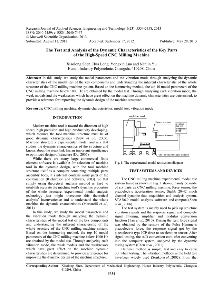
Research Journal of Applied Sciences, Engineering and Technology 5(23): 5354-5358, 2013 ISSN: 2040-7459; e-ISSN: 2040-7467 © Maxwell Scientific Organization, 2013 Submitted: August 11, 2012 Accepted: September 17, 2012 Published: May 28, 2013 The Test and Analysis of the Dynamic Characteristics of the Key Parts of the High-Speed CNC Milling Machine Xiaolong Shen, Hua Long, Yongxin Luo and Nanlin Yu Hunan Industry Polytechnic, Changsha 410208, China Abstract: In this study, we study the modal parameters and the vibration mode through analyzing the dynamic characteristics of the modal test of the key components and understanding the inherent characteristic of the whole structure of the CNC milling machine system. Based on the hammering method, the top 10 modal parameters of the CNC milling machine below 1000 Hz are obtained by the modal test. Through analyzing each vibration mode, the weak modals and the weaknesses which have great effect on the machine dynamic characteristics are determined, to provide a reference for improving the dynamic design of the machine structure. Keywords: CNC milling machine, dynamic characteristics, modal test, vibration mode INTRODUCTION Modern machine tool is toward the direction of high speed, high precision and high productivity developing, which requires the tool machine structure must be of good dynamic characteristics (Drew et al., 2005). Machine structure’s experimental modal analysis that studies the dynamic characteristics of the structure and knows about the weak link has an important significance to optimized design of structure (Du, 2005). While there are many large commercial finite element software is available for selection of machine tool in the dynamic design, with the tool machine structure itself is a complex containing multiple parts assembly body, it’s internal contains many parts of the combination (Richardson and Schwarz, 2003). So that simply using theoretical analysis method is hard to establish accurate the machine tool’s dynamic properties of the whole structure, experimental modal analysis technology just might overcome this theoretical analysis’ inconvenience and to understand the whole machine the dynamic characteristics (Martarelli et al., 2011). In this study, we study the modal parameters and the vibration mode through analyzing the dynamic characteristics of the modal test of the key components and understanding the inherent characteristic of the whole structure of the CNC milling machine system. Based on the hammering method, the top 10 modal parameters of the CNC milling machine below 1000 Hz are obtained by the modal test. Through analyzing each vibration mode, the weak modals and the weaknesses which have great effect on the machine dynamic characteristics are determined, to provide a reference for improving the dynamic design of the machine structure. Fig. 1: The experimental modal test system diagram TEST SYSTEMS AND DEVICES The CNC milling machine experimental modal test system frame as shown in Fig. 1 shows, mainly be made of six parts as CNC milling machine, force sensor, the piezoelectric acceleration sensor, Siglab 20-42 much channel dynamic data acquisition and analysis system, STAR6.0 modal analysis software and compute (Shen et al., 2006). The test system is mainly used to pick up structure vibration signals and the response signal and complete signal filtering, amplifier and modulus conversion function (Tan et al., 2010). During the test, force signal was obtained by the sensors of the Pulse Hammer's piezoelectric force, the response signal got by the piezoelectric type ICP three to acceleration sensor. After signal testing, the A/D conversion card after converting into the computer system, analyzed by the dynamic testing system (Chen et al., 2001). Hammer method is simple, fast and easy to carry out when testing. The vibration methods in the field test have been widely used (Sonko et al., 2002). From the Corresponding Author: Xiaolong Shen, Department of Mechanical Engineering, Hunan Industry Polytechnic, Changsha 410208, China 5354 Res. J. Appl. Sci. Eng. Technol., 5(23): 5354-5358, 2013 actual situation and the structure characteristics of the machine itself, big force can be produced behind the strength hammer added the counterweight and energy is scattered in wide frequency range, using the strength hammer can produce the shock power which is enough to inspire the vertical machining center, suiting the machine tool’s experimental modal analysis (Shen et al., 2010). Pulse hammer’s specific models using the American PCB company's 086D05 types, the most strongly in pulse hammer for 44 kN, sensor sensitivity is 0.23 mV/N, hammer’s weight is 3.2 kN, choosing nylon hammer mat, it’s incentive frequency cap of 1.7 KHz, pulse width for 2-3 ms. Each instrument, sensors and A/D device are corrected before the test (Shen et al., 2011). Sensor adopts the CA-YD-152 TE piezoelectric ICP which produced by Jiangsu united electronics Co., LTD., specific models for. Test plan: Test point arrangement: Vertical CNC milling machine has five major components: column, spindle box, beach, bed saddle and base. According to the machine and the structure size to identify the number of geometry measuring point, choosing the principle of putting in place and not miss modal for the principle and as far as possible simplified (Liu et al., 2004). For each geometry point to measure it’s three-response to get three dimensional vibrations model, the measuring-point to be analyzed for measuring is three times geometry points and arrangements as follows: selected 204 geometric structures in machine model, by the analysis of 612 point transfer function (Jenq-Shyong and Kwan-Wen, 2005). Each point numbers beginning with the part number, as shown in Table 1. The choice of supporting conditions: Machine tool is always under a certain boundary condition, because the same machine tools under various constraints and boundary conditions will have different modal parameters and properties. Therefore, reasonable selections of machine tool in the state of the constraint and boundary conditions have important meaning. All test of CNC milling machine is in the assembly workshop of the machine tool, the base is directly put on the rigid iron pad, its constraint is similar to the constraints of the real work and boundary condition. Before the test, adjusting the position of the machine components, making it in a commonly used work position (Muciente et al., 2010). The beach and bed saddle are adjusted to the center direction along the X and in the middle of the base direction along the Y; the end of the spindle is located in the surface 40 cm place. TEST METHOD There are generally two kinds of test methods can choose in Hammering test (Amer and Bauomy, 2009): Table 1: The point distribution of modal test model Parts Part no. Point no. Point no. Pillar 1 63 101-172 Base 2 56 201-256 Workbench 3 15 317-331 Saddle bed 4 36 407-424, 431-448 Spindle box 5 34 501-512, 523-534, 555-556, 601-608 The point numbers is discontinuous Fig. 2: Force hammers incentive position • • Using a fixed pulse hammer for single point excitation, while continuously moving the three acceleration sensor measuring response signal Fixing the 3 acceleration sensors and continuously moving the hammer to percussion machine tool at every point. The first method is used to choose 555 points front-end of the spindle box as shown in Fig. 2 Machine tools were divided into 204 geometric measuring point, the workload is bigger, in order to improve the reliability of the test data and save test time, using a magnetic sensor for localization way to fixed, at the same time measure X, Y, Z three direction of the vibration acceleration signal, the sensor X, Y, Z direction same as the CNC milling machine coordinate system’s direction (Belouettar et al., 2008). When application of data acquisition system for sampling, each point using five times in the frequency domain trigger to average processing. Analysis the choice of sampling frequency band: Trial before determine the test analysis frequency band and discovering that the main tool machine structure modal concentrated in 1000 Hz, higher modes has little influence to machine tool’s dynamic characteristics, almost can be ignored. So, the analysis of the band set to 0 to 1000 Hz. And then set the acquisition system’s cutoff frequency, such already can reduce data collection and analysis work and enhance the modal parameter identification accuracy. 5355 Res. J. Appl. Sci. Eng. Technol., 5(23): 5354-5358, 2013 frequency can’t be lower than 2 time of highest frequency analysis. For the response signal of vertical CNC milling machine structure, according requirements of not happen frequency, sampling frequency are collected at the request of the 2560 Hz. To hammer the produce of the pulse force, 2560 Hz high sampling frequency is also used. At the same time, force signal strength window, acceleration signal and Exponential window, to reduce leakage error. FRF: 118y:555y x10 -4 118y:G4 6 mag(Ga)/Ibs 5 4 3 2 Elimination of the test interference factors: One of the important premises of using the experimental modal analysis technology research the dynamic characteristics of machine tool is machine structure should meet various hypothetical conditions and range. Special to a variety combination of the complex structure machine system, to ensure the reliability and effectiveness of the test, modal test should be done before the following preparation test: 1 0 100 200 300 400 500 600 700 800 900 1000 x: linear Hertz (a) Amplitude frequency curve in 118 point at Y FRF: 410z:555y x10 -4 410z:G4 mag(Ga)/Ibs 8 • 6 4 • 2 0 100 200 300 400 500 600 700 800 900 1000 x: linear Hertz (b) Amplitude frequency curve in 410 point at Z Fig. 3: Modal test part of the test data In order to avoid frequency aliasing, according to Shannon sampling theorem, signal’s collection Mutual test: Modal analysis is based on the theory of basis on linear system. This requires the machine structure’s nonlinear error be small before testing. In pulse vibration test, it can be easily inspected by knocking each other. Coherence test: The coherent function (γ2) can be calculated by the vibration force spectrum F (f) and acceleration of the frequency spectrum A (f). γ 2 is between 0-1 and it is characterized the reliability of the results and the estimation of the evaluation of the transfer function. Test and analysis Test data: Test data collection is frequency response function, in order to obtain all the modal parameters Fig. 4: STAR6.0 modal analysis process 5356 Res. J. Appl. Sci. Eng. Technol., 5(23): 5354-5358, 2013 Table 2: CNC milling machine vibration model and basic characteristic No f (Hz) Damping ratio (%) Vibration model describing 1 60.03 9.68E-01 The central column is bending and exercising along the direction Y; the column bottom and base joints dislocation 2 65.91 1.53 Bending of the column parts and moving up and down of the base of column 3 148.09 7.02E-01 To and fro swing of the machine tool 4 206.97 9.04E-01 Up and down of sliding base and workbench; to and fro swing of the column 5 288.66 9.33E-01 The swinging along the direction before and after of the column, base and the spindle component. The moves up and down of sliding base and workbench 6 387.41 1.04 The moves up and down of sliding base and workbench, the twist movement of column 7 504.55 1.24 Up and down of the base, the spindle, the sliding base and workbench; the twist and bending movement of column, concave and produce dislocation phenomenon on a left, the moves to and fro of the whole machine 8 572.52 1.61 The swing movement of the whole machine, high order bending movement of column 9 878.14 9.58E-01 Combined motion of column for high order bending and high order reverse 10 932.53 2.99E-01 The swinging of the column from side to side, torsion of the sliding along the X axis and modal shape information, it need enough transfer function curve to measure, we can get 204×3 transfer function in the test. When measurements the transfer function curve, removed the overload and combo signals, to try to improve the reliability of the signal. The test data is in 0-1000 Hz as shown in Fig. 3. Modal analysis: Modal analysis chooses frequency domain method of orthogonal polynomials and experimental data analysis, the concrete process completed by STAR6.0, as shown in Fig. 4. The mode of CNC milling machine test data processing, on 1000 Hz mainly exists within 10 large peaks. STAR6.0 identified by the first ten order modal parameters and the description of the vibration mode as shown in Table 2, mode vibration as shown in Fig. 5. Modal Criteria (MAC), can be used to compare the same group two modal vector is correct, the modes of the MAC value between relatively small almost close to 0, explaining the trial to get various order of modal parameters is effective and reliable. (a) The first stage 60.03 Hz (c) The fourth stage 206.97 Hz • The column swings around the Z or column to obvious twist sports occurs at the first order (60.03 Hz), the second order (95.91 Hz), the fourth order (206.97 Hz), the seventh order (504.55 Hz) ,especially in the first and second order modal frequency place along the direction of the central column and bending vibration more apparent. Considering the modal test spindle box part is located in the middle of column, most machines under the condition of spindle box part also located in middle of column. Column in these few order of frequency vibration characteristics of the machine tool of the machining accuracy has obvious effect, so the stiffness of the column in the change of machine structure should be strengthened. In the first, second and eight order modal frequencies, the column and base dislocate apparently in the column and the base of the joints. Obviously, this is because of the bolt insufficient (d) The seventh stage 504.55 Hz Fig. 5: The mode vibration of CNC milling machine stages ANALYSIS OF THE TEST RESULTS • (b) The second stage 60.03 Hz • • • 5357 prestressing force between the column and the joint surface of the base, so the problem of joints should be seriously considered in the process of changing the structure. In the fifth, sixth order modal frequency, in the saddle bed both ends swing along the direction of the up and down. Considering the characteristics of the CNC milling machine tools itself, or in the processing of large mould, the modal can bring about relative displacement between tool and work piece, thus influencing the quality of the processing of the machine tools. It belongs to the harmful mode and we should avoid it as far as possible. The table and the bed in various order saddle modal frequency vibration is consistent, without apparent dislocation, therefore, it doesn’t have great effect on the machining precision of machine. It can infer that the stiffness between machine bed saddle and the table is very modest and the way of the joint is quite reasonable. The third order (148.09 Hz) modal frequency, the spindle box bobbing vibration is bigger and so the relative displacement is bigger, other modal Res. J. Appl. Sci. Eng. Technol., 5(23): 5354-5358, 2013 • frequency spindle box part does not have larger vibration, visible in the third order modal frequency components of car-body main vibration mainly. Seen from seventh order (504.55 Hz) modal shape, machine tool were largely to and fro of the whole machine tools and shaking. Commonly, machine tool machine's shaking vibration modal usually will not seriously affect machining quality and we can see that this order frequency and the base of the 499.63 Hz solid frequency close to, so the modal also want to try to overcome. CONCLUSION To test the dynamic analysis technology is mainly used for determination of the inherent structure modal of the two basic parameters: natural frequencies and modal shape and it shows the structure of the free vibration characteristics, according to the experimental modal analysis technology from the natural frequency and vibration mode animation shows the inherent characteristic of the structure. If you know the structure of the inherent frequency, the improvement of the structure design can be carried on to make the natural frequency of the machine tool in the actual processing machine avoids situations external incentives of frequency: • • The results of the experimental modal analysis can be seen in the 1, 2, 4 and 7 modes, machine parts. And bending the torsion of column of vibration quite obvious, it is mainly because of the column of anti-bending ability and inadequate. Watching the experimental modal analysis of each get order modes found, machine tool and the base of the combining part have stiffness insufficient, which mainly have the bolt pre-tightening force is insufficient or the connecting bolt unreasonable layout of the cause. Through analysis of experimental modal, you can component bending stiffness distribution, thus providing the reference for machine tool design. the machine tool’s also learn about each and torsion stiffness necessary basis and the dynamics optimization ACKNOWLEDGMENT This project is supported by Science and Technology Fund of Hunan Provincial Science and Technology Department (No. 2011GK3090) and Vocational Education Research Subject of China Machinery Industry Education Association (ZJJX11ZZ015). REFERENCES Amer, Y.A. and H.S. Bauomy, 2009. Vibration reduction in a 2DOF twin-tail system to parametric excitations. Commun. Nonlinear Sci. Numer. Simul., 14(2): 560-573. Belouettar, S., L. Azrar and E.M. Daya, 2008. Active control of nonlinear vibration of sandwich piezoelectric beams. Simplif. Approach. Comp. Struct., 86(3-5): 386-397. Chen, G.Q., J.X. Yuan and J.A. Ni, 2001. A displacement measurement approach for machine geometric error assessment. Int. J. Mach. Tool Manuf., 41: 149-150. Drew, M., K. Thai Pelt and H. Zhang, 2005. In Metal Cutting Machine Tools Dynamic Characteristics. Mechanical Industry Publisher, Beijing, China. Du, Y., 2005. MSY7115 Surface Grinder Experimental Modal Analysis and the Dynamic Characteristics Modify. Kunming University of Science and Technology, China, pp: 24-32. Jenq-Shyong, C. and C. Kwan-Wen, 2005. Bearing load analysis and control of a motorized high speed spindle. Int. J. Mach. Tools Manuf., 45(12-13): 1487-1493. Liu, H.L., B. Li and H.M. Shi, 2004. Title. J. Huazhong Univ. Sci. Technol., 31: 32-35. Martarelli, M., P. Castellini and C. Santolini, 2011. Laser Doppler vibrometry on rotating structures in coast-down: Resonance frequencies and operational deflection shape characterization. Measur. Sci. Technol., 22(11): 115106. Muciente, M., F.J. Alcala, R. Alcala and J. Casillas, 2010. A case study for learning behavior sin mobile robotics by evolutionaryfuzzysystems. Exp. Syst. Appl., 37: 1471-149. Richardson, M. and B. Schwarz, 2003. Scaling mode shapes obtained from operating data. Sound Vib., 28: 37-39. Shen, X.L., L.X. Zhang and G.Y. Chen, 2006. Experimentation research for the flutters in high speed grinding. Mod. Manuf. Eng., 6: 119-120. Shen, X.L., L.X. Zhang, H. Long and Z.X. Zhou, 2010. Title. Appl. Mech. Mater., 34-35: 1936-1939. Shen, X.L., Y.X. Luo, L.X. Zhang and H. Long, 2011. Natural frequency computation method of nonlocal elastic beam. Adv. Mater. Res., 156-157: 1582-1585. Sonko, O., T. Toshiyuki, N. Hironori and K. Tomizo, 2002. Development of aball step-gauge and an interferometric stepper used for ball-plate calibration. Precis. Eng., 26(2): 214-216. Tan, W.J., Z.X. Zuo and Y.T. Liu, 2010. Title. Mechanical Design, 10: 38-41. 5358

